Eureka AIR delivers breakthrough ideas for toughest innovation challenges, trusted by R&D personnel around the world.

Blasthole plug and method

A blast hole blocking and blast hole technology is applied in the field of blast hole clogging, which can solve the problems of poor drilling powder clogging effect, etc., and achieve the effect of solving the problem of poor blasting effect, saving materials and good blasting effect.

Inactive Publication Date: 2013-12-18
CHINA GEZHOUBA (GRP) FIRST ENG CO LTD
View PDF5 Cites 19 Cited by
  • Summary
  • Abstract
  • Description
  • Claims
  • Application Information

AI Technical Summary

Problems solved by technology

[0004] The technical problem to be solved by the present invention is to provide a blast hole blockage and its method, which can prevent the drill powder from entering the charging section, and after further improvement, can also solve the problem of poor plugging effect of the drill powder

Method used


Image

  • Blasthole plug and method
  • Blasthole plug and method
  • Blasthole plug and method

Examples


Embodiment 1

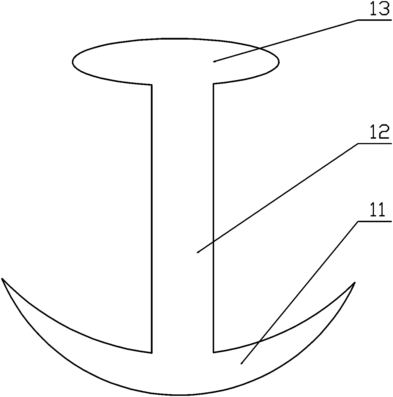
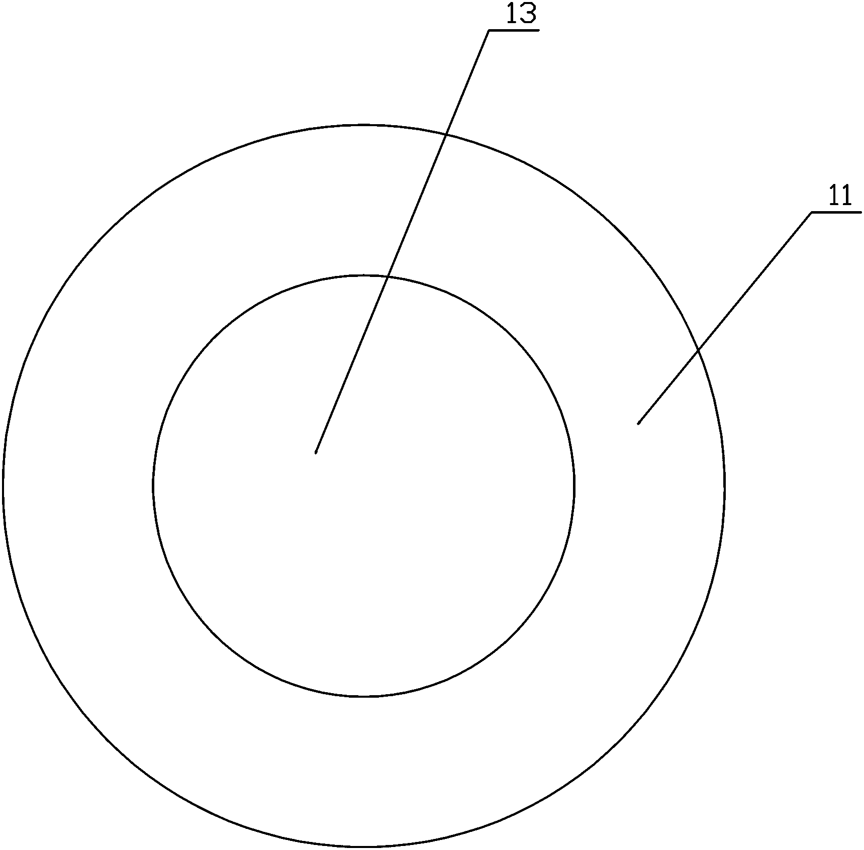
[0026] Such as figure 1 , 2 Among them, a blasthole plug, the front end of the plug 1 is provided with a concave arc-shaped portion 11, and the concave arc-shaped portion 11 gradually changes from thick to thin from the central axis portion to the edge portion, and the longitudinal section of the concave arc-shaped portion 11 is inward. Concave arc, the diameter of the inner concave arc portion 11 is greater than the diameter of the blasthole 2, the diameter of the rest of the plugging 1 is smaller than the diameter of the blasthole 2, and the height of the plugging 1 is greater than the diameter of the blasthole 2, so as to prevent the plugging 1 from Flip inside hole 2. With this structure, when the plug 1 is placed in the blasthole 2, the structure of the concave arc portion 11 enables the plug 1 to move in one direction only in the blasthole 2, thereby improving the plugging effect, and can form a Sealing to prevent substances in the plugging section, such as drilling po...

Embodiment 2

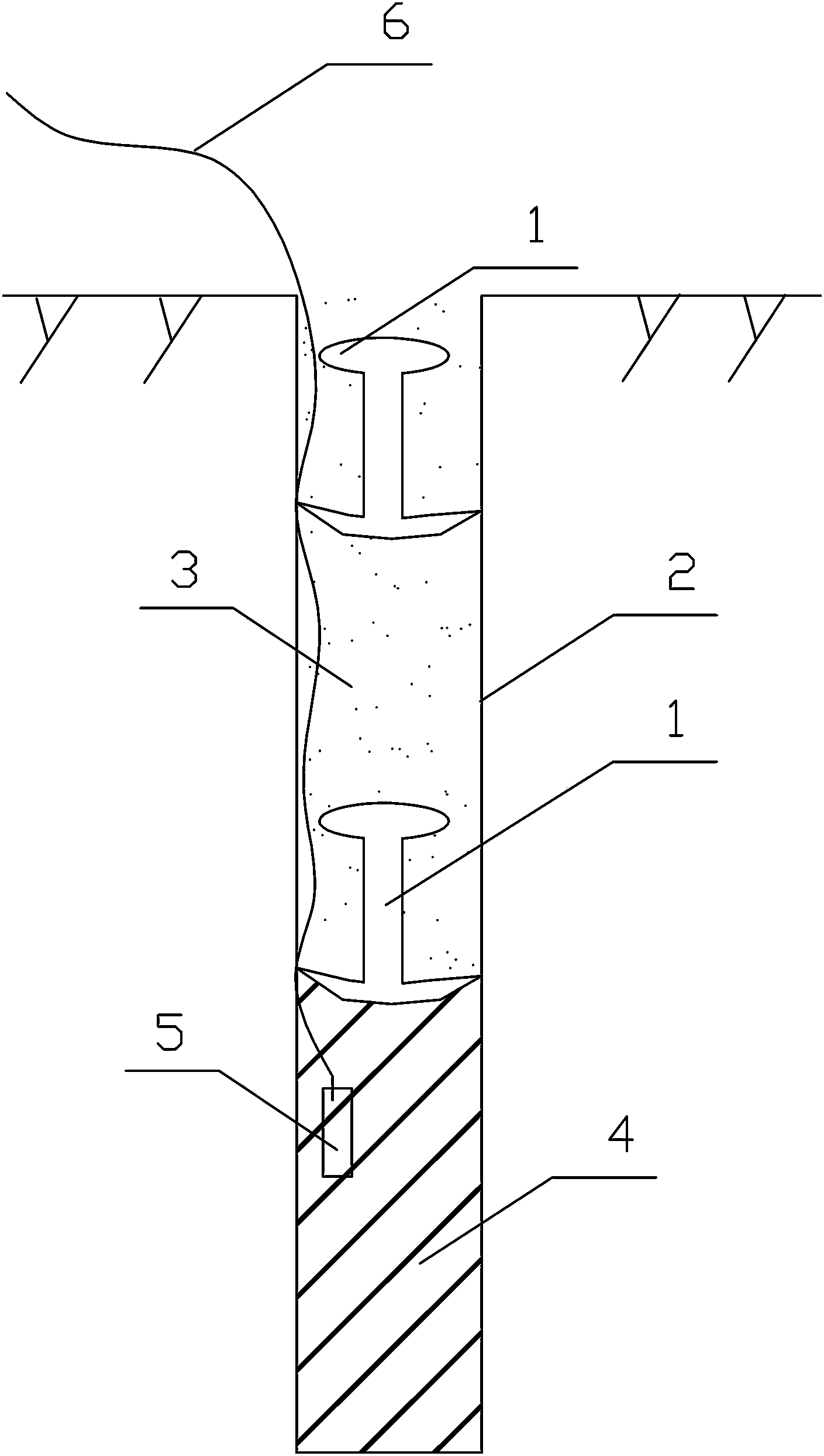
[0031] Such as Figure 4 Among them, a method for drilling and blasting using the above-mentioned blasthole plugging, comprising the following steps:

[0032] 1. Drilling to form the blast hole 2 and then charging;

[0033] 2. Load the detonator 5 and draw the detonator lead wire 6;

[0034] 3. Put the concave arc portion 11 of the plug 1 downward into the blast hole 2, and insert it with a gun stick until the device is in close contact with the explosive;

[0035] 4. Fill in the drill powder 3 and compact it. When compacting, use gun sticks for compaction.

[0036] Realize adopting drilling powder to plug blast hole through above-mentioned steps. Since the diameter of the concave arc-shaped portion 11 of the plug 1 is slightly larger than that of the blast hole, and because of its special shape, it can only move in one direction toward the bottom of the hole, so it can effectively prevent the drill powder from entering the charge section. In addition, due to its one-way m...


PUM


Abstract

Disclosed is a blasthole plug. A concave arc-shaped part is arranged at the front end of the plug and thinned gradually from the axis to the edge, a longitudinal section of the concave arc-shaped part is in a shape a concave arc, the diameter of the concave arc-shaped part is larger than that of a blasthole, the diameters of the rest parts of the plug are smaller than that that of the blasthole, and the height of the plug is larger than the diameter of the blasthole. A method for drilling and blasting by the blasthole plug includes the steps: firstly, charging after drilling to form the blasthole; secondly, mounting a detonator and leading out a detonator lead; thirdly, mounting the concave arc-shaped portion into the blasthole downwards; fourthly, filling drilling dust for compaction. Through the steps, the drilling dust is adopted to plug the blasthole. The drilling dust can be prevented from entering a charging section; in addition, due to one-way mobility, large resistance can be obtained during blasting, and thereby a blasting effect is better.

Description

technical field [0001] The invention relates to the field of drilling and blasting construction, in particular to a blasthole plugging method and a method thereof. Background technique [0002] At present, the well-known drilling and blasting blockages all require special blasting mud or clay, but the blockages in actual field operations are basically all local materials, and for the blasting site, because they are all rocks, there are few fine particles or clay, Therefore, gunners basically use the drill powder produced by drilling when they are blocked. The problems of directly using diamond powder are: (1) Since the diamond powder particles are very fine and loose, they will enter the charging section when blocked, thereby affecting the blasting effect. (2) Since the drill powder is loose, its blocking effect is not good, and it is easy to punch holes and release blasting energy from the orifice, resulting in poor blasting effect or blasting failure, or even accidents. ...

Claims


Application Information

Patent Timeline
IPC IPC(8): F42D1/18
Inventor 汤用泉张小兵王国胜周继红常国阁张小华胡方华
Owner CHINA GEZHOUBA (GRP) FIRST ENG CO LTD
Why Eureka
Eureka Blog
Learn More