
Motor-driven compressor

A technology of motor drive and compressor, applied in the direction of machine/engine, liquid fuel engine, connection with control/drive circuit, etc., can solve the problems of reducing the cooling performance of motor drive circuit and not easy to dissipate.

Inactive Publication Date: 2013-12-18
TOYOTA IND CORP
View PDF5 Cites 2 Cited by
  • Summary
  • Abstract
  • Description
  • Claims
  • Application Information

AI Technical Summary

Problems solved by technology

Furthermore, in particular, since the sealing member is located between the cover and the case, heat transferred from the motor drive circuit to the cover is less likely to be dissipated to the case
Therefore, the cooling performance of the motor drive circuit housed in the housing space is reduced

Method used


Image

  • Motor-driven compressor
  • Motor-driven compressor
  • Motor-driven compressor

Examples


Embodiment Construction

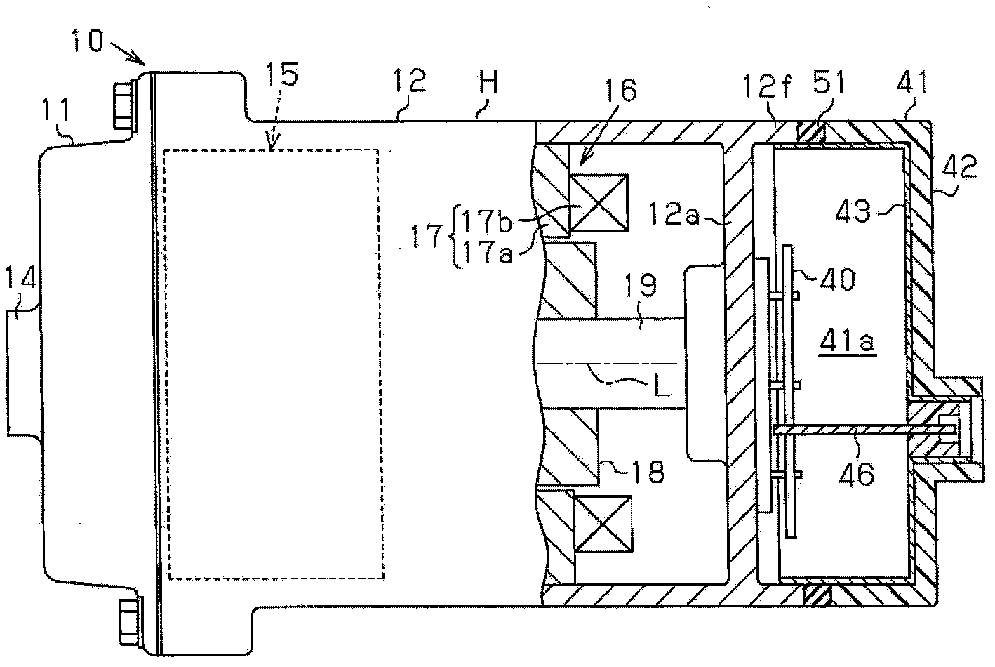
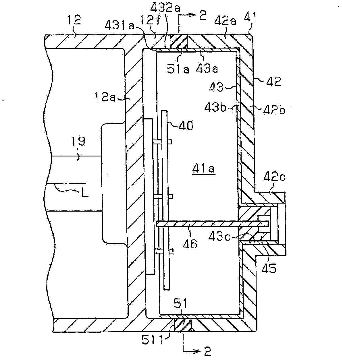
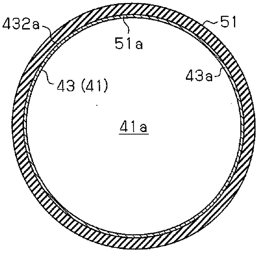
[0015] The following will refer to Figure 1A , Figure 1B with figure 2 A motor-driven compressor according to one embodiment will be described.

[0016] Such as Figure 1A Motor driven compressor 10 has a housing H as shown. The housing H includes a discharge housing member 11 made of aluminum (made of a metal material) and a suction housing member 12 made of aluminum (made of a metal material) joined to the discharge housing member 11 . The discharge housing member 11 is shaped as a cylinder with a closed upper portion. The suction housing member 12 is shaped as a cylinder with a closed bottom. A suction port (not shown) is formed in a peripheral wall of the suction housing member 12 and is connected to an external refrigeration circuit (not shown). A discharge port 14 is formed in the discharge housing member 11 and is connected to an external refrigeration circuit. The suction housing member 12 accommodates a compression part 15 for compressing refrigerant and an el...


PUM


Abstract

A motor-driven compressor includes a housing made of a metal material, a compression portion, an electric motor, and a cover. The compression portion and the electric motor are accommodated in the housing, and the cover is attached to the housing. The cover is formed by a plastic portion and a shield made of a metal material that intercepts electromagnetic noise. A motor drive circuit for driving the electric motor is accommodated in an accommodation space defined by the housing and the cover. An elastic sealing member is located between the housing and the cover. The shield includes an extended portion that extends toward the housing and is arranged inside the sealing member. The extended portion is in contact with the housing.

Description

technical field [0001] The present invention relates to a motor driven compressor. Background technique [0002] The motor-driven compressor includes a housing made of a metal material that accommodates a compression section that compresses refrigerant and an electric motor that drives the compression section. A cover is attached to the housing. The covering body defines an accommodating space, and a motor drive circuit for driving the electric motor is accommodated in the accommodating space. A sealing member is provided between the casing and the covering body. The sealing member prevents waste or water from entering the accommodating space through the interface between the housing and the cover. [0003] When the covering body is made of a metal material, the weight of the motor-driven compressor itself becomes heavy. In this regard, coverings made of plastic materials have been proposed to reduce the weight of the covering, thereby reducing the weight of the motor-dr...

Claims


Application Information

Patent Timeline
Patent Type & Authority Applications(China)
IPC IPC(8): F04B39/00
CPCF04B39/0027F04B39/06F04C23/008F04C27/008F04C29/047F04C18/0215F04C2240/808H02K11/0141F04B39/00F04C29/00H02K11/30
Inventor 深作博史
Owner TOYOTA IND CORP
Learn More