Isolation baffle mechanism of bypass switch
What is Al technical title?
Al technical title is built by PatSnap Al team. It summarizes the technical point description of the patent document.
A technology of isolating baffles and bypass switches, which is applied in the field of electromechanical manufacturing, can solve problems such as stagnation, large space occupation, and unsmooth operation, and achieve the effects of improved reliability, smooth operation, and reduced product volume
Active Publication Date: 2015-10-28
GUIZHOU TAIYONG CHANGZHENG TECH CO LTD
View PDF5 Cites 0 Cited by
Summary
Abstract
Description
Claims
Application Information
AI Technical Summary
This helps you quickly interpret patents by identifying the three key elements:
Problems solved by technology
Method used
Benefits of technology
Problems solved by technology
This structure requires high machining precision and assembly precision of parts, takes up a lot of space, does not run smoothly, and is prone to jamming
Method used
Image
Click on the blue label to locate the original text in one second.
Reading with bidirectional positioning of images and text.
Examples
Embodiment Construction
[0012] The bypass power transfer switch is mainly composed of the main switch and the bypass switch. The main switch can be drawn out and inserted into the box of the bypass switch, and the isolation baffle mechanism mainly protects the bypass switch. The isolation baffle can be opened and closed at any time as needed.
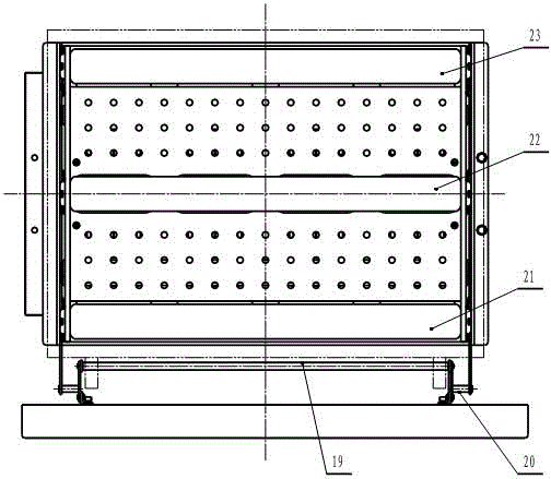
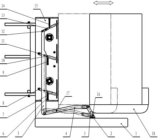
[0013] Such as figure 1 , figure 2 As shown, an isolation baffle mechanism of a bypass switch, the isolation baffle structure is a symmetrical frame structure, mainly composed of a bottom plate 1, a bracket 2, a crank 3, a lever 4, a connecting rod 5, a tension spring 6, and a swing rod 1. 7. Hinge axis one 8, tension spring two 9, swing rod two 10, hinge axis two 11, hinge axis three 12, swing rod three 13, tension spring three 14, mounting plate 15, hinge axis four 16, hinge axis five 17 , Push plate 18, connecting rod 19, hinge shaft six 20, baffle one 21, baffle two 22, baffle three 23. The bracket 2 is fixed on the bottom plate 1, the hinge shaft 416 is ...
PUM
Abstract
The invention relates to an isolating baffle mechanism for a bypass switch. The isolating baffle mechanism is of a symmetrical frame structure, and mainly comprises a base plate, a bracket, a crank, a lever, a joint lever, a tension spring 1, an oscillating bar 1, a hinged shaft 1, a tension spring 2, an oscillating bar 2, a hinged shaft 2, a hinged shaft 3, an oscillating bar 3, a tension spring 3, a mounting plate, a hinged shaft 4, a hinged shaft 5, a pushing plate, a connecting rod, a hinged shaft 6, a baffle 1, a baffle 2 and a baffle 3; when a main body switch is pushed in, the pushing plate at the bottom of the main body switch touches the upward front end of the lever firstly, along with the forward moving of the pushing plate, the front end of the lever oscillates downwards under the action of a downward pressing force, the other end of the lever oscillates upwards so as to push the joint lever to move upwards, along with the upward moving of the joint lever, two oscillating bars below the joint lever oscillate upwards, and the upmost oscillating bar moves downwards. Because a force exerted on the lever is far greater than a tensile force of the spring, the baffles move to corresponding directions under the driving of the oscillating bars. The baffle mechanism disclosed by the invention runs smoothly, and the reliability of the baffle mechanism is also greatly improved.
Description
Technical field [0001] The invention belongs to the field of electromechanical manufacturing, and particularly relates to an isolation baffle mechanism of a bypass switch. Background technique [0002] A draw-out type power transfer switch with bypass is mainly composed of a main switch and a bypass switch. The main switch can be drawn and inserted into the box of the bypass switch. The isolation baffle mainly protects the bypass switch: one is to protect personal safety and avoid casualties; the other is to prevent foreign objects from entering and avoid current short-circuits. Damage, fire and other accidents. [0003] When the main switch is inserted, the isolation baffle needs to be opened automatically so that the main switch contact is inserted into the bypass switch contact, the main switch and the bypass switch are connected, and the isolation baffle has no protective effect. When the main switch is pulled out, the isolation baffle closes automatically, the bypass switch ...
Claims
Application Information
Patent Timeline
Application Date:The date an application was filed.
Publication Date:The date a patent or application was officially published.
First Publication Date:The earliest publication date of a patent with the same application number.
Issue Date:Publication date of the patent grant document.
PCT Entry Date:The Entry date of PCT National Phase.
Estimated Expiry Date:The statutory expiry date of a patent right according to the Patent Law, and it is the longest term of protection that the patent right can achieve without the termination of the patent right due to other reasons(Term extension factor has been taken into account ).
Invalid Date:Actual expiry date is based on effective date or publication date of legal transaction data of invalid patent.