Pipe structure

A technology for pipe fittings and pipe assemblies, which is applied in the field of improvement of pipe fitting structures, can solve the problems of affecting support strength and service life, increase connecting parts, increase set steps, etc. The effect of structural strength

Active Publication Date: 2015-12-02
林信志
View PDF6 Cites 0 Cited by
  • Summary
  • Abstract
  • Description
  • Claims
  • Application Information

AI Technical Summary

Problems solved by technology

[0003] The above-mentioned support tube assembly is usually composed of a plurality of metal sleeves, which can be divided into round tubes and square tubes. The four sides of the square tube have the advantages of stress concentration and are not easy to deform. However, the production of square tubes The cost is obviously higher than that of round tubes, so most furniture uses round tubes
[0004] Among the socketing methods between the sleeves of the traditional support tube assembly, the one with lower cost inserts the sleeve 91 into the nozzle of another sleeve 92, such as Figure 14 As shown, the sleeve 92 has an enlarged diameter nozzle 921, and the other sleeve 91 has a reduced diameter end 911 that can be inserted into the expanded diameter nozzle 921, so that the expanded diameter nozzle 921 and the reduced diameter end 911 The contact surface is inclined; but its disadvantage is that when the support pipe assembly bears the heavy pressure from above, the expanded diameter nozzle 921 of the sleeve 92 is easy to move down along the inclined contact surface. The expansion deformation makes the gap between the inner wall of the expanded nozzle 921 and the outer wall of the reduced diameter end 911 larger, resulting in loosening and skewing of the sleeves 91 and 92 when they are nested together, which affects the support strength and service life.
[0005] another example Figure 15 As shown, the above-mentioned diameter-expanding nozzle can also be omitted, and the reduced-diameter end 931 of the sleeve 93 is directly inserted into the nozzle 941 of another sleeve 94, but after the sleeve 93 is processed to form the reduced-diameter end 931, It is also easy to form an inclined surface 932 between the outer wall of the sleeve 93 and the reduced-diameter end 931; in this way, when the support pipe assembly bears the heavy pressure from above, the nozzle 941 of the sleeve 94 is also easy to follow The downward movement of the inclined surface 932 and the expansion and deformation will also cause the sleeves 93, 94 to become loose and skewed when they are nested together, which will affect the support strength and service life.
[0006] In order to overcome the above-mentioned problem of poor support strength when the bushings are stacked with each other and load-bearing, there are already a variety of technologies for positioning the bushings with each other on the market, including setting connecting pieces between the nozzles of the bushings, and The nozzle and the outer wall of the end of the casing are respectively provided with threads for screw assembly; however, the above-mentioned mutual nesting and positioning technology of the traditional casing must increase connecting parts or process threads, which will only increase the complexity of components and the production cost. , and the addition of sets of steps, the assembly is more inconvenient, obviously there is a need for improvement
[0007] In addition, the above-mentioned furniture that can be disassembled and expanded is generally convenient for transportation and storage. Consumers do not need professional skills and tools to disassemble, expand, and transport by themselves. Taking the above-mentioned sink as an example, consumers can use the sink, The base and the casing of the support tube assembly can be freely disassembled and boxed, which is beneficial to handling, carrying and storage, saves the volume of carrying and storage, and can quickly assemble the sink after arriving at the destination; but its disadvantage is that the protrusion at the bottom of the sink The bottom of the outlet tank is easy to be dented and damaged by external force collision, and the casing is also easy to collide with the protruding tank bottom of the water tank during handling and loading to cause damage, which needs to be improved urgently

Method used


Image

  • Pipe structure
  • Pipe structure
  • Pipe structure

Examples


Embodiment Construction

[0077] Embodiments of the present invention will be described below with reference to the drawings. Elements and features described in one drawing or one embodiment of the present invention may be combined with elements and features shown in one or more other drawings or embodiments. It should be noted that representation and description of components and processes that are not related to the present invention and known to those of ordinary skill in the art are omitted from the drawings and descriptions for the purpose of clarity.

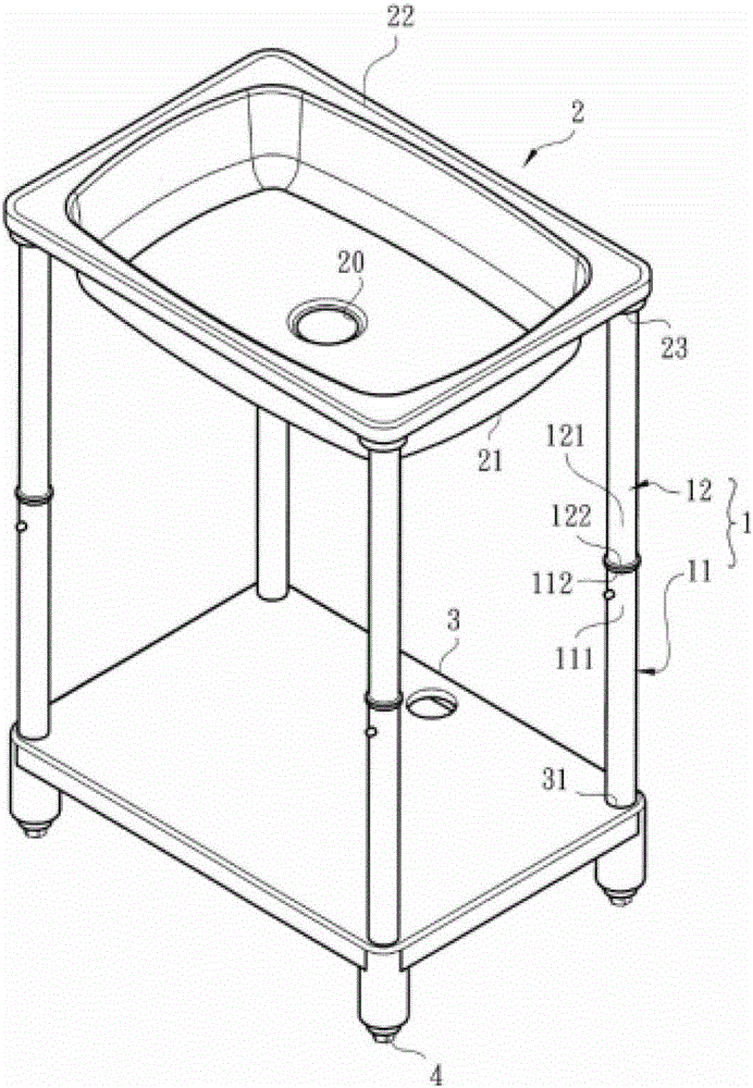
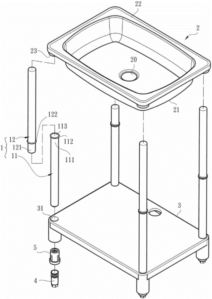
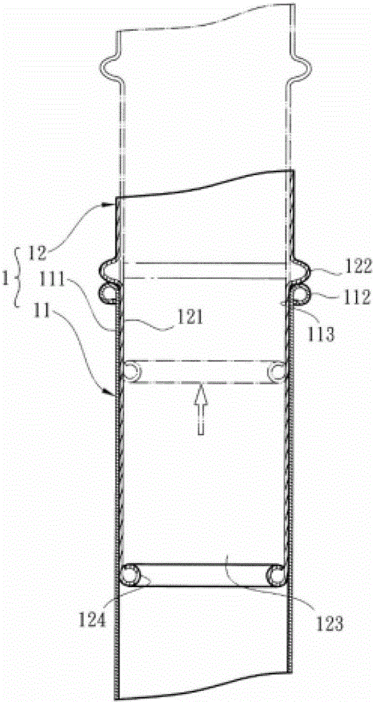
[0078] Please refer to Figure 1 to Figure 3 , which discloses the drawings of the first embodiment of the present invention, wherein, figure 1 It is a perspective view of the first embodiment of the present invention, figure 2 for figure 1 three-dimensional exploded view, image 3 for figure 1 Partial sectional view of embodiment.

[0079] The structure of the pipe fittings of the present invention is illustrated by the above drawings, a...


PUM


Abstract

The invention provides a pipe fitting structure which can improve the location and supporting strength on the premise of simplifying components. The pipe fitting structure comprises a pipe assembly consisting of a first sleeve and a second sleeve, wherein the first sleeve and the second sleeve are assembled in a bushing manner; one end of the first sleeve forms an outer bushing end, and one end of the second sleeve forms an inner inserting end; an outer wall, close to a pipe end and having a space, of the inner inserting end is annularly provided with at least one protruded part in an external extension manner, and the protruded part is larger than the inner diameter of the outer bushing end; when the outer bushing end and the inner inserting end are bushed, the tail end of the opening of the outer bushing end is stopped by the protruded part, and the edge of the opening of the outer bushing end forms an outer coiled ring end coiled outwards, so that the opening of the outer bushing end locates and supports the protruded part of the inner inserting end by the outer coiled ring end, and the opening of the outer bushing end is prevented from bearing the weight of the inner inserting end to deform. Therefore, the pipe fitting structure has the advantages of prolonged service life, simple components, convenience in assembly and the like.

Description

technical field [0001] The present invention relates to the improvement of a pipe fitting structure, and in particular relates to a method of curling the edge of the nozzle of the sleeve outward to form an outwardly curled ring end, so that the nozzle of the sleeve can strengthen the positioning of another sleeve through the outwardly curled ring end, The assembly structure of supporting strength. Background technique [0002] At present, the clothes hangers, storage racks, bookshelves, TV cabinets and sinks on the market, which can be disassembled and retracted, usually need to carry heavy loads, so most of them use metal pipes as supporting components; for example, the metal pipe structure of the above-mentioned traditional sink The design is mainly to install a metal tube support tube assembly at the bottom of the four end corners of a stainless steel water tank to support the ground, and the bottom ends of the support tube assembly are combined with a base to make the st...

Claims


Application Information

Patent Timeline
Patent Type & Authority Patents(China)
IPC IPC(8): F16B7/08E03C1/326
Inventor 林信志
Owner 林信志
Why Eureka
Try Eureka