
Speed limiting trigger

A trigger, a pair of technology, applied in the direction of elevators, transportation and packaging, etc., can solve problems such as unstable and reliable operation, high-strength interference, danger, etc., to achieve the effect of reducing installation and construction risks, safe and reliable structure, and reducing manufacturing costs

Inactive Publication Date: 2013-12-11
谭锦泉
View PDF7 Cites 5 Cited by
  • Summary
  • Abstract
  • Description
  • Claims
  • Application Information

AI Technical Summary

Problems solved by technology

The speed limiter used must be installed on the top of the equipment, especially the installation of the speed limiter on the top of the construction elevator frame has the danger of working at heights, and is not conducive to installation, inspection and maintenance.
The speed limiter installed on the top of the traditional construction elevator cage leads to defects in use and installation, and no one has thought of the design of the trigger before. The industry urgently needs a safe and reliable speed limit trigger that can be installed on the top of the cage device
[0003] Traditionally, there are also electronic speed limiters. Because electronic speed detection is easily affected by high-intensity interference in the industrial environment, and the operation is unstable and reliable, electronic speed limit triggers are not accepted by the national safety supervision department.

Method used


Image

  • Speed limiting trigger
  • Speed limiting trigger
  • Speed limiting trigger

Examples


Embodiment Construction

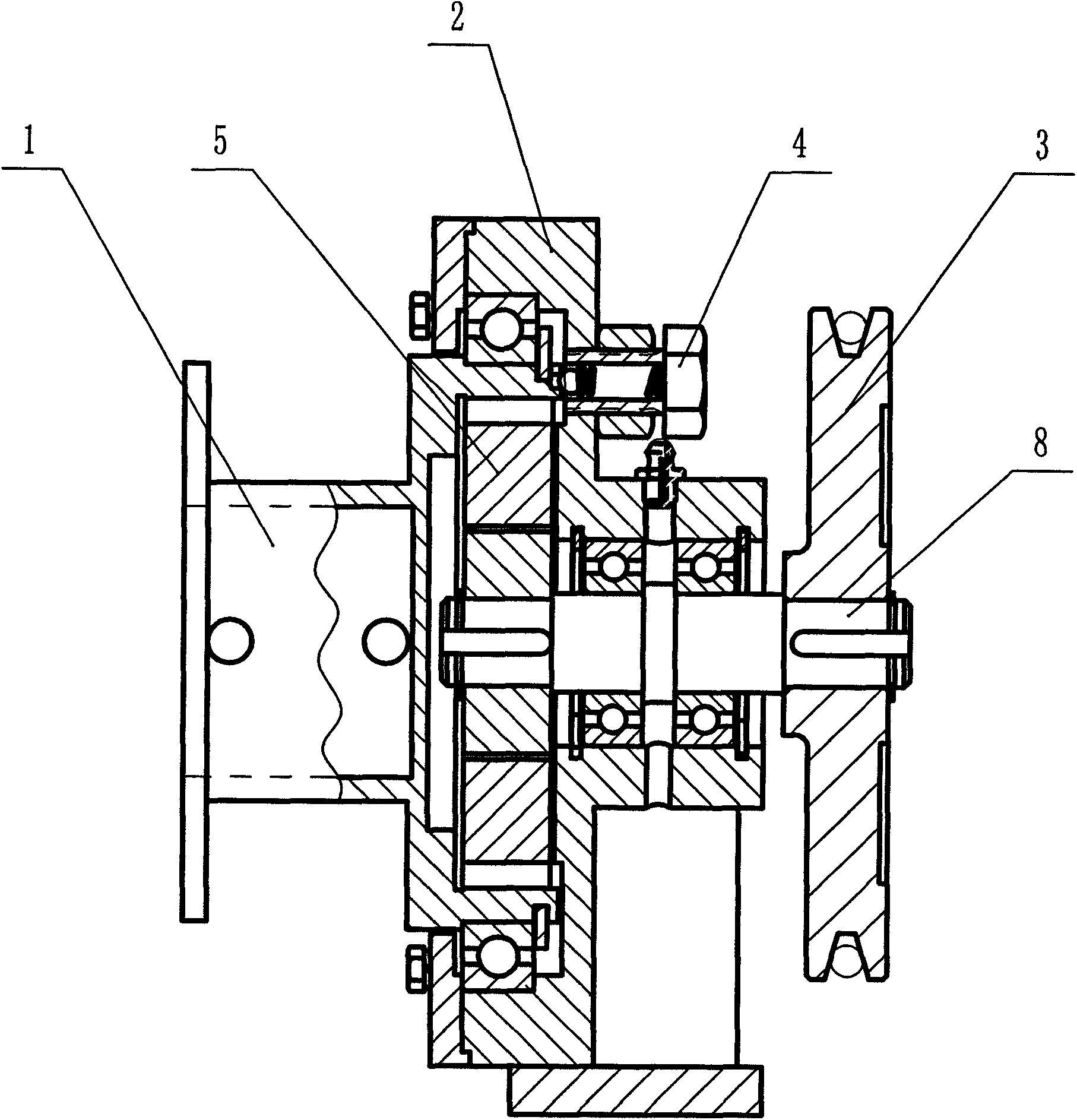
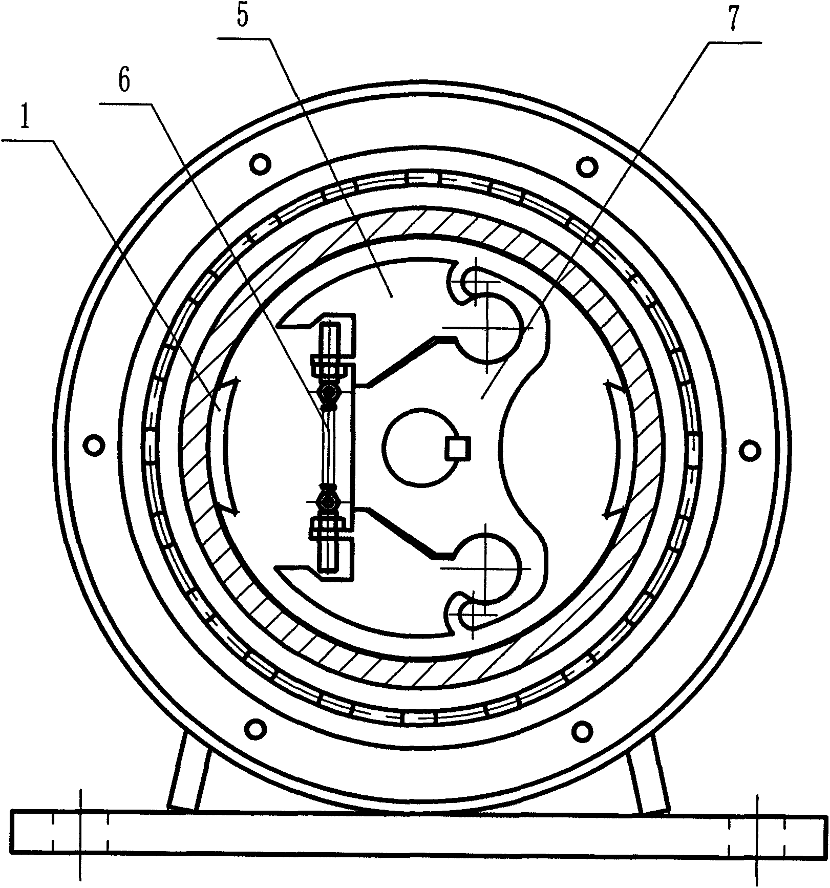
[0022] Reference figure 1 with figure 2 , The first embodiment of the present invention is a speed limit trigger, including a speed limit trigger seat 2, a trigger drum with ratchet teeth fixed on the speed limit trigger seat 2, a speed measuring wheel 3, a pair of centrifugal Block, centrifugal block seat 7, adjusting spring 6 and main shaft 8. The speed measuring wheel 3 is coaxially connected with the centrifugal block seat 7 through the main shaft 8. One end of a pair of centrifugal blocks is respectively clamped on both sides of the centrifugal block seat 7. The other end is connected to each other by an adjusting spring 6, and the pair of centrifugal blocks are also provided with ratchet teeth respectively.

[0023] The second embodiment of the present invention is a speed limit trigger, which includes a speed limit trigger seat 2, a trigger drum with ratchet teeth fixed on the speed limit trigger seat 2, a speed measuring wheel 3, a centrifugal block 5, The centrifugal bl...


PUM


Abstract

The invention discloses a speed limiting trigger which comprises a speed limiting trigger base, a triggering coiling block fixed to the speed limiting trigger base and provided with ratchet wheel teeth, a speed measurement wheel, a pair of centrifugal blocks, a centrifugal block base, an adjusting spring and a main shaft. The speed measurement wheel is connected with the centrifugal block base coaxially through the main shaft. One end of each centrifugal block is clamped on one side of the centrifugal block base, the other end of one centrifugal block and the other end of the other centrifugal block are connected through the adjusting spring, and the pair of centrifugal blocks are respectively provided with ratchet wheel teeth as well. The speed limiting trigger is simple in structure, safe, reliable and capable of being installed at the top of a hanging cage of an elevator so that the triggering and braking functions for the speed limitation of the hanging cage can be achieved. The speed limiting trigger is good in performance and can be widely applied to the industries of elevators or construction mechanical equipment.

Description

Technical field [0001] The invention relates to the technical field of safety of lifting and hoisting equipment, in particular to the triggering part of a safety protection device for preventing stalling and falling of a cage (car) of a simple construction elevator. Background technique [0002] The traditional speed limiter that relies on wire ropes to transmit signals must be installed on the top of the equipment. The signal wire rope of the speed limiter is wound into a closed wire rope system. The power to trigger the action of the safety gear comes from the weight of the heavy hammer so that the wire rope and the tachometer wheel form a certain degree. The friction force, as the friction force to pull the safety gear, is determined by the weight of the heavy hammer. When the cage (car) overspeeds, the speed limiter will stop the signal wire rope running synchronously, and the cage will continue to move downward to pull the safety gear to stop the cage. The speed limiter use...

Claims


Application Information

Patent Timeline
Patent Type & Authority Applications(China)
IPC IPC(8): B66B5/04
Inventor 王志文
Owner 谭锦泉
Learn More