
Novel aerofoil by utilizing magnus effect

A wing and a new type of technology, applied in the aviation field, can solve the problems of low lift efficiency, ineffective effects, and increased wing lift, and achieve the effects of reducing heat loss, reducing runway requirements, and reducing wing area

Inactive Publication Date: 2013-12-11
NORTHWESTERN POLYTECHNICAL UNIV
View PDF5 Cites 25 Cited by
  • Summary
  • Abstract
  • Description
  • Claims
  • Application Information

AI Technical Summary

Problems solved by technology

Aerodynamic lift refers to the use of flaps and other devices to increase wing camber, area, and delay airflow separation. Fundamentally speaking, it only changes the shape and area of ​​the wing. The disadvantages of this type of lift increase method are: Efficiency is usually low and the mechanism is complicated. Opening the flaps will not only bring greater resistance, but also bring greater nose-down moment, which requires higher trimming capabilities of the aircraft's horizontal tail; while the power boost method is to let the engine The jet flow or the slipstream behind the propeller flows through the wing, and the high-speed airflow is deflected downward by deflecting the trailing edge flap, thereby increasing the lift of the wing. The disadvantage is that the increased lift is essentially the engine or propeller. The thrust is obtained by turning, the size of this additional lift cannot be adjusted, and the effect is usually not obvious
[0003] In short, the lift of the existing wing is usually determined by the flight speed when the shape and angle of attack are fixed, while the traditional way of increasing the lift has the disadvantages of low lift efficiency, complicated mechanism or non-adjustable additional lift, which makes it possible to realize short-distance aircraft. It is more difficult to take off and land and cruise at low speed

Method used


Image

  • Novel aerofoil by utilizing magnus effect
  • Novel aerofoil by utilizing magnus effect
  • Novel aerofoil by utilizing magnus effect

Examples


Embodiment Construction

[0025] Describe the present invention below in conjunction with specific embodiment:

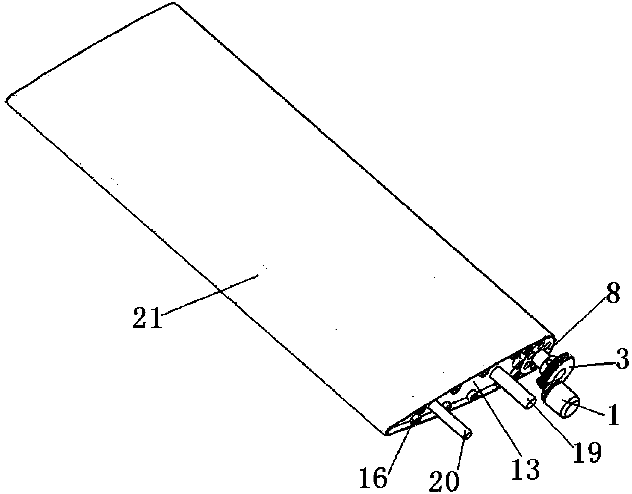
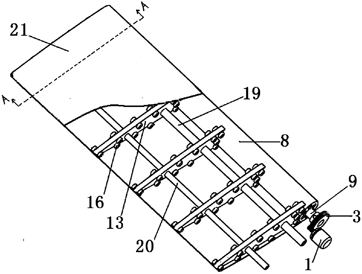
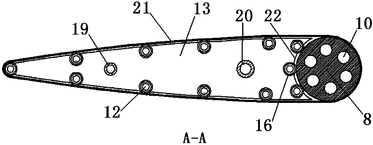
[0026] The novel wing utilizing the Magnus effect in this embodiment includes a skin 21, a rib 13, a beam, a wing leading edge roller 8 and a driving device.

[0027] Refer to attached figure 1 , attached figure 2 And attached Figure 5 , what the wing adopts is a rectangular airfoil, on the surface of the wing there is a skin 21 tensioned along the shape of the wing, and the skin adopts a flexible material. The chord length of the wing is 22cm, and the span length is 60cm. Six ribs 13 parallel to each other are evenly distributed along the spanwise direction of the wing, and there are through front beam installation holes on the ribs at 8cm and 18cm from the leading edge point respectively. 14 and rear beam installation hole 15, its aperture is 1cm and 0.8cm respectively; The mounting hole is bonded and fixed with the wing rib 13, and the other end close to the motor 1 is bonded with p...


PUM


Abstract

The invention discloses a novel aerofoil by utilizing a magnus effect. The novel aerofoil by utilizing a magnus effect comprises a flexible skin, wing ribs, beams, an aerofoil leading edge roller and a driving device, wherein the driving device drives the aerofoil leading edge roller to rotate; the front ends of the wing ribs are of circular arc concave structures; circular arc concave surfaces are provided with rolling bearings; the aerofoil leading edge roller is positioned in the circular arc concave structures at the front ends of the wing ribs, and are matched with the wring ribs through the rolling bearings; a plurality of rolling bearings are also installed at the peripheral edges of the wing ribs; the flexible skin wraps an aerofoil framework consisting of the aerofoil leading edge roller, the wing ribs and the beams; the aerofoil leading edge roller can drive the flexible skin to slide around the aerofoil framework. According to the novel aerofoil, the defect that the resistance is high as a cylindrical aerofoil is utilized for generating magnus lift force in the prior art is overcome; compared with the traditional aerofoil, the novel aerofoil has the advantages that when the aerofoil is in low-speed flight, only the rotation speed of a motor is required to be regulated, so that the slide speed of the skin is increased, also the aerofoil can obtain greater lift force; the loading weight is increased, and short-distance taking-off and landing are achieved, and the track requirement is lowered.

Description

technical field [0001] The invention belongs to the field of aviation technology, in particular to a novel wing utilizing the Magnus effect. Background technique [0002] The function of the wings is to generate lift to balance the weight of the aircraft when it is flying in the air. The surface skin of the existing wing is fixed. When the wing shape and angle of attack are constant, the lift of the wing is completely determined by the flight speed of the aircraft. Therefore, the lift of the wing is limited during the take-off, landing and low-speed stages of the aircraft. , in order to increase the lift of the wing, the way that usually adopts is to install the lift increasing device. At present, commonly used increasing lift devices include aerodynamically increasing lift and power increasing lift. Aerodynamic lift refers to the use of flaps and other devices to increase wing camber, area, and delay airflow separation. Fundamentally speaking, it only changes the shape an...

Claims


Application Information

Patent Timeline
IPC IPC(8): B64C3/00
Inventor 唐继伟胡峪宋笔锋
Owner NORTHWESTERN POLYTECHNICAL UNIV
Learn More