
Shaft end location and locking structure of stirrer

A technology for positioning and locking mixers, applied to cement mixing devices, clay preparation devices, chemical instruments and methods, etc., can solve the vibration of the stirring shaft, affect the operation and service life of the mixer, and cannot effectively ensure the centering and positioning of the stirring shaft, etc. problems, to achieve the effect of overcoming complex structure, improving running stability and simple structure

Inactive Publication Date: 2013-12-11
XINJIANG YUXIN CONCRETE
View PDF8 Cites 2 Cited by
  • Summary
  • Abstract
  • Description
  • Claims
  • Application Information

AI Technical Summary

Problems solved by technology

This utility model has the function of sealing and ensuring coaxiality, but in the actual use process, the shaft end structure of this utility model cannot effectively ensure the centering and positioning of the stirring shaft, and it often occurs after a period of use. Unstable rotation such as shaking or shaking of the stirring shaft seriously affects the normal operation and service life of the mixer

Method used


Image

  • Shaft end location and locking structure of stirrer
  • Shaft end location and locking structure of stirrer
  • Shaft end location and locking structure of stirrer

Examples


Embodiment Construction

[0026] In order to further explain the technical solutions of the present invention, specific examples are given below to illustrate in detail.

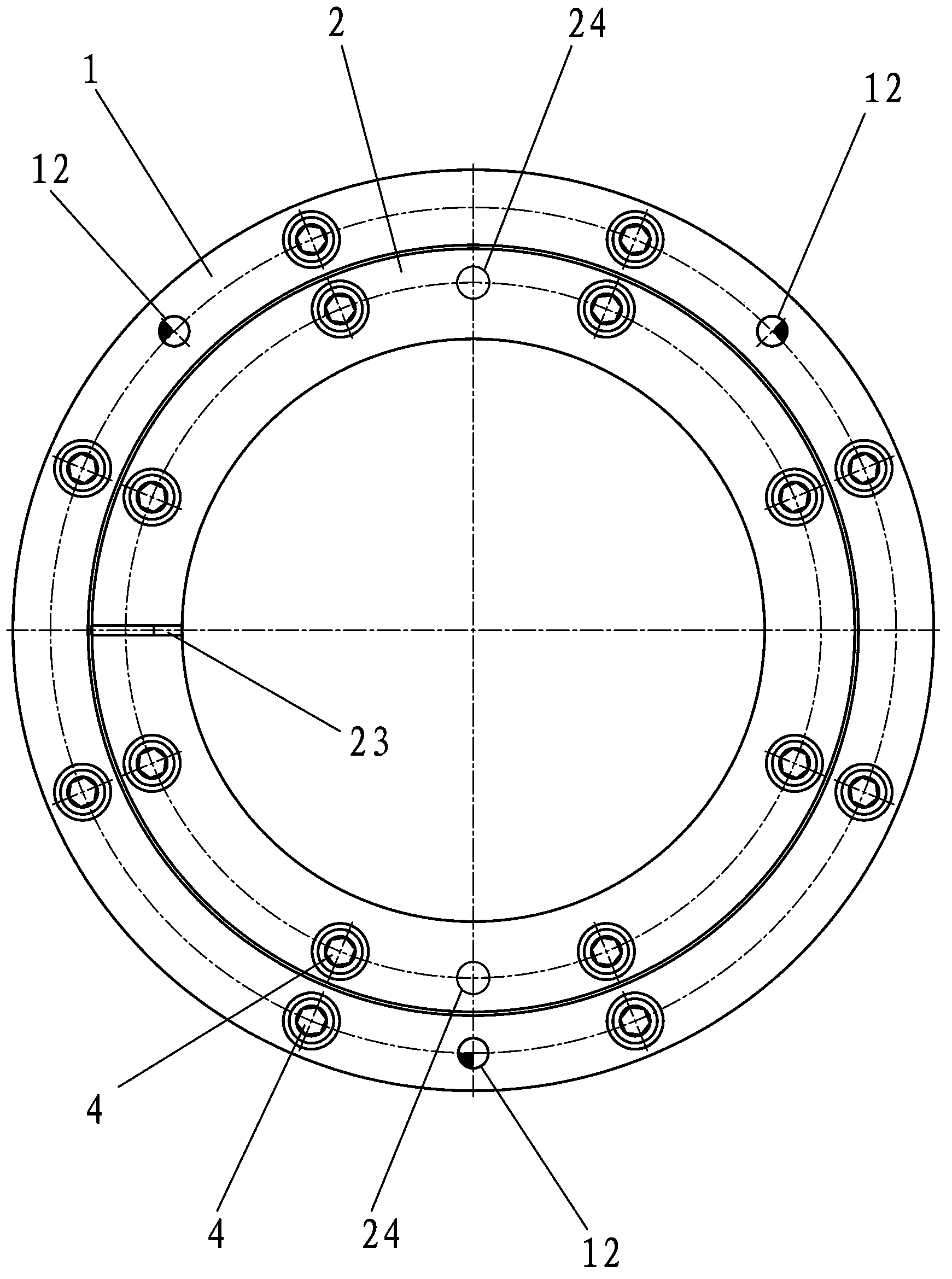
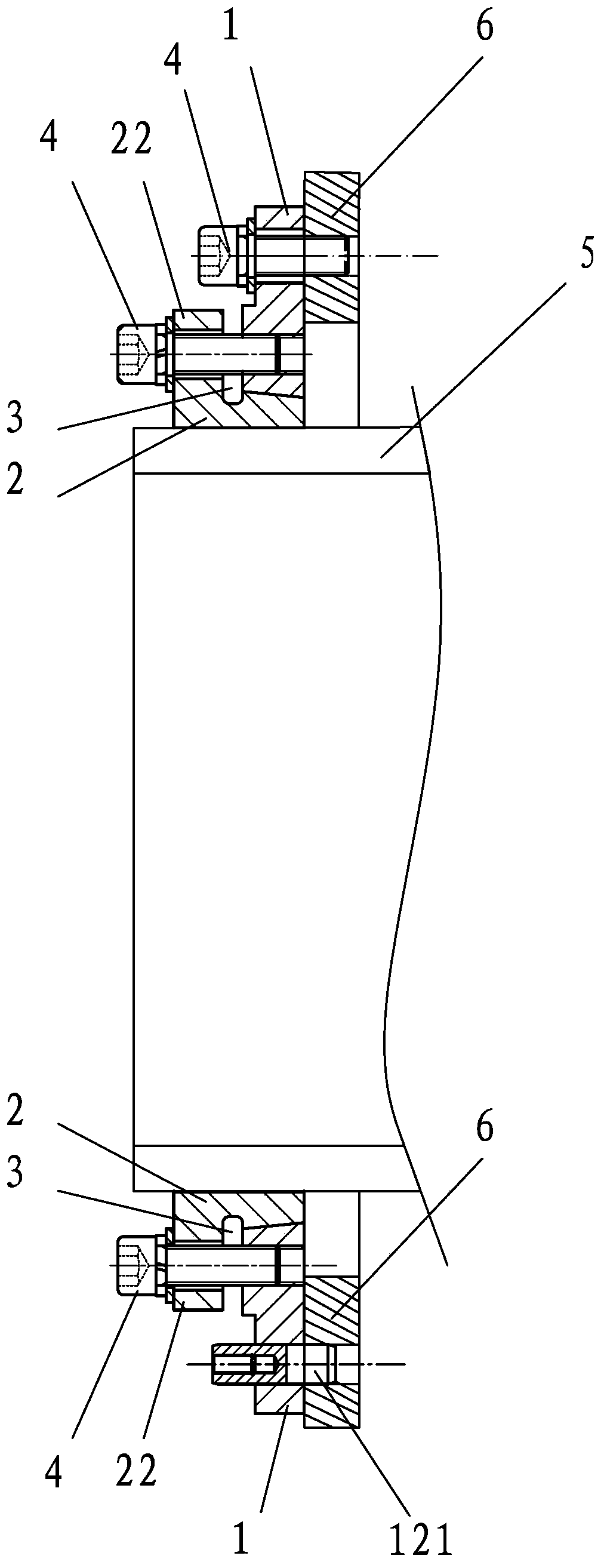
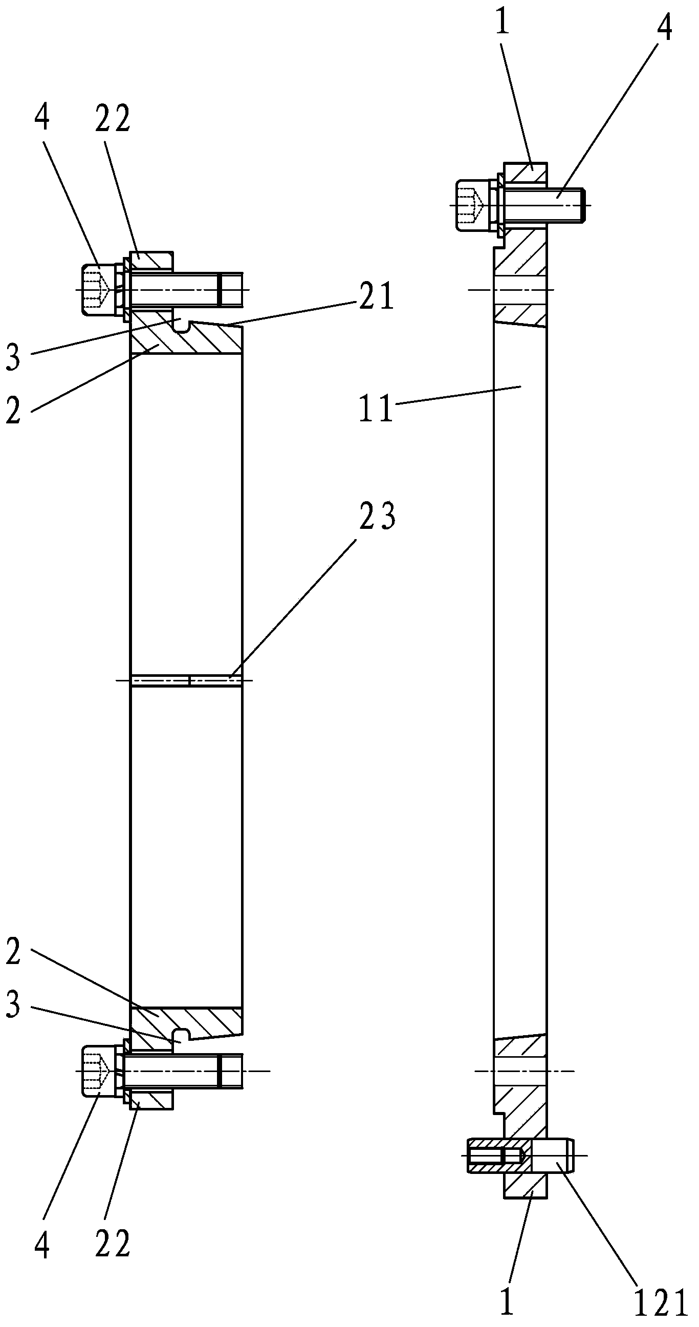
[0027] A shaft end positioning and locking structure of the mixer of the present invention, such as Figure 1-3 As shown, it includes positioning taper sleeve 1 and locking inner cone 2.

[0028] The positioning cone sleeve 1 is fixed with the end wall of the mixer, the locking inner cone 2 is installed with the shaft end bearing seat 5 of the mixer, and the locking inner cone 2 is locked together with the positioning cone sleeve 1; the positioning cone sleeve 1 is formed by Conical bushing 11 tapering from outside to inside, locking the inner cone 2 to form a conical bushing 21 matched with the conical bushing 11 from outside to inside, during use, the positioning cone bushing 1 is fixed on the end wall of the mixer Above, the conical sleeve head 21 of the locking inner cone 2 is matched and installed in the conical sleeve hole 11 ...


PUM

PropertyMeasurementUnit
widthaaaaaaaaaa

Abstract

The invention provides a shaft end location and locking structure of a stirrer, which comprises a location cone sleeve and an internal locking cone which are locked together, wherein a cone sleeve hole is formed in the location cone sleeve; and a cone sleeve head is formed on the internal locking cone. Therefore, the structure breaks through a structural form of the traditional similar device; the location cone sleeve is fixed on an end wall of the stirrer; the cone sleeve head is mounted in the cone sleeve hole in a matched manner; due to automatic centripetence of matched cone cambered surfaces of the cone sleeve hole and the cone sleeve head, when the internal locking cone moves inwards along the cone sleeve hole till a male cone of the cone sleeve head is completely adhered with a female cone of the cone sleeve hole, the centers of the internal locking cone and the location cone sleeve are coincided; the internal locking cone can be located in the center of the location cone sleeve by locking the internal locking cone and the location cone sleeve; further, the purpose of centering a shaft end bearing support of the stirrer is achieved; and compared with the prior art, the structure has a self-centering location function, and is convenient and quick to operate, simple, novel and reasonable in structure, and high in practicability.

Description

technical field [0001] The invention relates to a shaft end structure of a stirring shaft in the field of mixers such as concrete, in particular to a positioning and locking structure for the shaft end of a mixer that can be automatically centered. Background technique [0002] The shaft end positioning of the stirring shaft of concrete and other mixers determines the degree of smooth rotation and smooth operation of the stirring shaft, which in turn affects the working performance of the entire mixer. The traditional shaft end structure, such as the Chinese utility model patent CN200420062945.8, discloses a horizontal shaft The shaft end seal and supporting device of the stirring shaft of the vertical mixer, which includes the shaft end sealing device of the stirring shaft and the supporting device, both of which are placed on the stirring shaft of the horizontal shaft mixer, positioned by the boss, and connected tightly by the connecting piece. This utility model has the f...

Claims


Application Information

Patent Timeline
Patent Type & Authority Applications(China)
IPC IPC(8): B28C5/00
Inventor 王建军陈建凡
Owner XINJIANG YUXIN CONCRETE
Learn More