
Controllable lockable protection switch, switch control system and lithium battery

A protection switch and control switch technology, applied in the electronic field, can solve problems such as limited functions and imperfect system security.

Active Publication Date: 2013-12-04
江阴赋锦信息技术有限公司
View PDF7 Cites 3 Cited by
  • Summary
  • Abstract
  • Description
  • Claims
  • Application Information

AI Technical Summary

Problems solved by technology

[0002] The current electronic industry and new energy industry are developing rapidly, especially the development of the lithium-ion battery industry, but the system security is not perfect. The current circuit board protection has a similar thermal protection switch, but the function is limited.

Method used


Image

  • Controllable lockable protection switch, switch control system and lithium battery
  • Controllable lockable protection switch, switch control system and lithium battery
  • Controllable lockable protection switch, switch control system and lithium battery

Examples


Embodiment 1

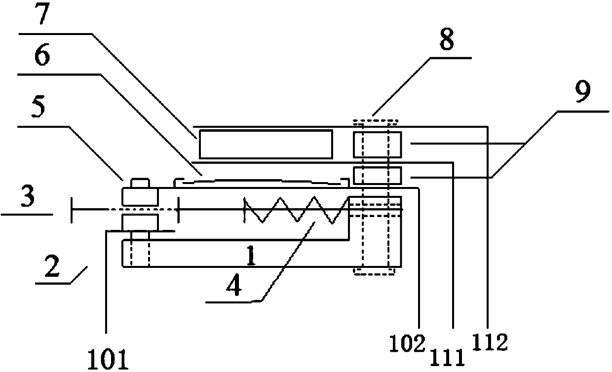
[0047] see figure 1 , the present invention discloses a controllable lockable protection switch, the protection switch mainly includes: a first contact 5, a second contact 2, a bimetal 6, a heating unit 7, a locking mechanism 3; the bimetal The sheet 6 is connected to the first contact 5 , and the first contact 5 is opposite to the second contact 2 .

[0048] The protection switch also includes a base 1 , a fixing rivet 8 , and a gasket 9 , and the gasket 9 is set on the fixing rivet 8 . The second contact 2 is fixed on one end of the base 1 (for example, it can be fixed by direct riveting), and the second contact 2 is connected to the power supply. Fixed rivets 8 fix the heating unit 7, bimetal 6, and elastic mechanism 4 on the other end of the base 1; One end is connected to the first contact 5, and the first contact 5 is connected to the power supply; the elastic mechanism 4 is arranged under the bimetal 6, one end of which is fixed on the fixed rivet 8, and the other end...

Embodiment 2

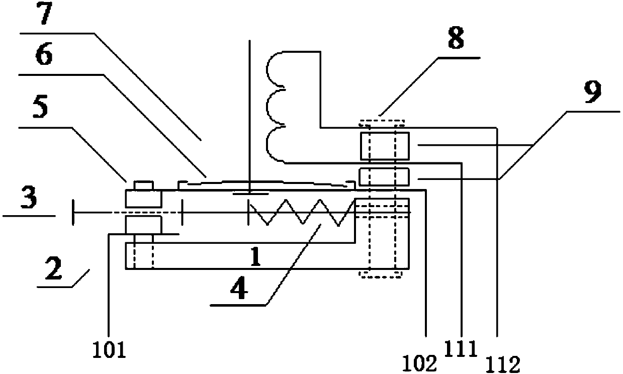
[0059] see image 3 , The difference between this embodiment and Embodiment 1 is that in this embodiment, the heating unit in Embodiment 1 is replaced by an electromagnetic coil, which can reduce the heating of the circuit, and the heat generation is small.

Embodiment 3

[0061] see Figure 4 The difference between this embodiment and Embodiment 1 is that in this embodiment, the locking mechanism is a heating controller, which controls the heating unit to keep heating, so that the bimetal is always in a tilted state, preventing the first contact from contacting the second The contacts are closed.

[0062] At this time, the locking mechanism 3 and the locking spring in the first embodiment may not be installed. When the above-mentioned structure is not installed, the connecting wires 111, 112 of the heating unit 7 (certainly also electromagnetic coils) must be energized all the time when locking; When the locking mechanism 3 is installed and the locking spring is separated and locked, it is only necessary to energize the connection lines 111 and 112 of the heating unit 7 for a short time, and the locking mechanism 3 is used to maintain the locking after separation, so that the locking can be achieved with zero power consumption. .


PUM


Abstract

The invention discloses a controllable lockable protection switch, a switch control system and a lithium battery. The controllable lockable protection switch comprises a first contact, a second contact, double metal pieces, a heating unit or a solenoid coil, and a locking mechanism. The double metal pieces are connected with the first contact, the first contact and the second contact are arranged oppositely, the heating unit or the solenoid coil is arranged close to the double metal pieces, the double metal pieces are controlled through the heating unit or the solenoid coil to drive the first contact and the second contact to be connected or disconnected, and the locking mechanism is used for preventing the first contact and the second contact from being closed after the first contact and the second contact are disconnected. The heating unit or the solenoid coil is arranged to control the double metal pieces so that closing and breaking of the switch can be controlled, the locking mechanism is arranged, so that after the switch is broken, the switch is prevented from being closed again, the protection effect on a whole circuit is achieved, and after the protection switch of the battery loses efficacy, explosion caused by the fact that the battery is charged all the time is avoided.

Description

technical field [0001] The invention belongs to the field of electronic technology, and relates to a protection switch, in particular to a controllable and lockable protection switch; at the same time, the invention also relates to a control system of a controllable and lockable switch. Lithium battery for lockable switch control system. Background technique [0002] The current electronic industry and new energy industry are developing rapidly, especially the development of lithium-ion battery industry, but it is not perfect for system safety. The current circuit board protection has a similar thermal protection switch, but the function is limited. [0003] The thermal protection switch must be protected when the ambient temperature of the circuit is too high, and it will automatically recover when the temperature drops. Especially in the circuits of lithium-ion batteries, it is very important to protect and lock out faults under extreme conditions, especially in the case ...

Claims


Application Information

Patent Timeline
Patent Type & Authority Applications(China)
IPC IPC(8): H01H37/02H01H37/52H01M10/42
CPCY02E60/12Y02E60/10
Inventor 蒋闯
Owner 江阴赋锦信息技术有限公司
Learn More