
Hydraulic cylinder stroke testing device

A technology of hydraulic oil cylinder and testing device, which is applied in the direction of fluid pressure actuating device, etc., can solve the problems of complex structure and low detection accuracy of the detection device, and achieve the effects of easy control and measurement, improvement of testing accuracy and cost saving.

Inactive Publication Date: 2013-12-04
上海爱德特检测设备制造有限公司
View PDF7 Cites 3 Cited by
  • Summary
  • Abstract
  • Description
  • Claims
  • Application Information

AI Technical Summary

Problems solved by technology

[0004] In view of the shortcomings of the prior art described above, the purpose of the present invention is to provide a hydraulic cylinder stroke test device for solving the problems of complex structure and low detection accuracy of the detection device in the prior art

Method used


Image

  • Hydraulic cylinder stroke testing device
  • Hydraulic cylinder stroke testing device
  • Hydraulic cylinder stroke testing device

Examples


Embodiment Construction

[0035] The implementation of the present invention will be illustrated by specific specific examples below, and those skilled in the art can easily understand other advantages and effects of the present invention from the contents disclosed in this specification.

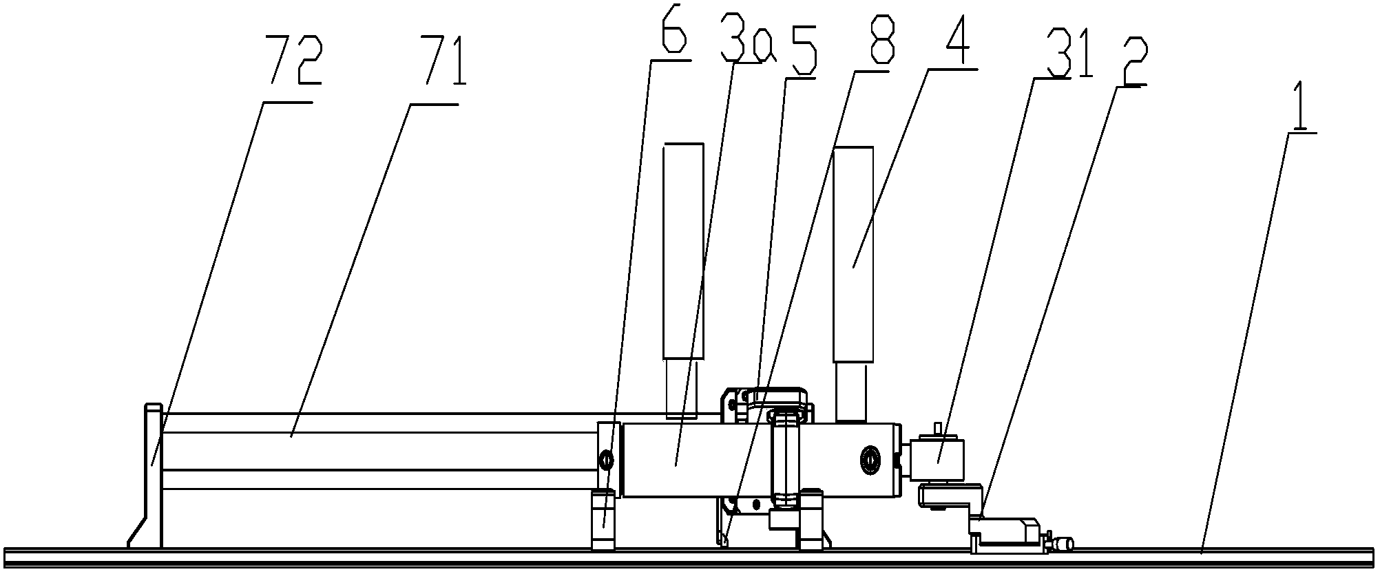
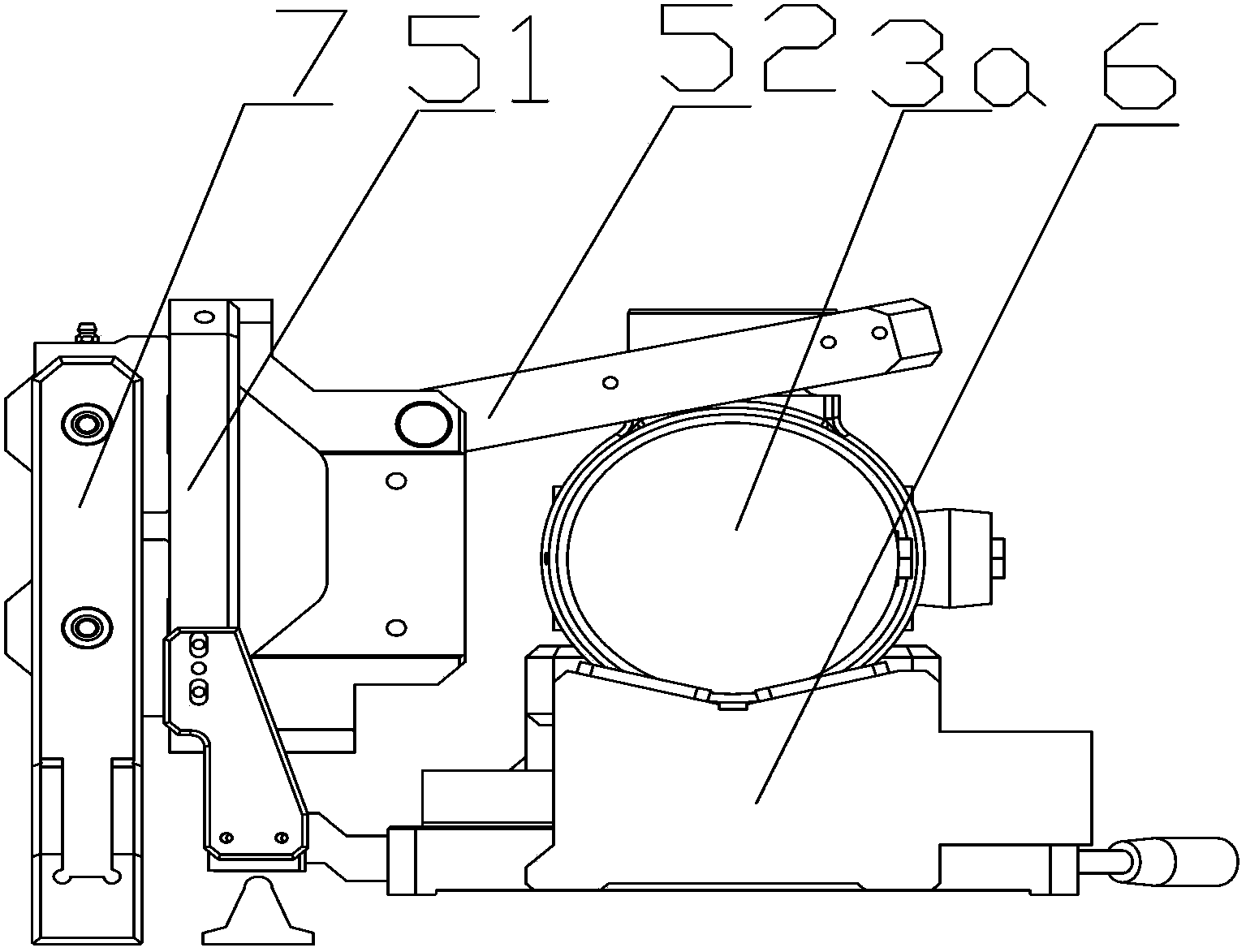
[0036] see Figure 1 to Figure 7 . It should be noted that the structures, proportions, sizes, etc. shown in the drawings attached to this specification are only used to match the content disclosed in the specification, for those who are familiar with this technology to understand and read, and are not used to limit the implementation of the present invention. Limiting conditions, so there is no technical substantive meaning, any modification of structure, change of proportional relationship or adjustment of size, without affecting the effect and purpose of the present invention, should still fall within the scope of the present invention. The disclosed technical content must be within the scope covered. At the sa...


PUM


Abstract

The invention provides a hydraulic cylinder stroke testing device. The hydraulic cylinder stroke testing device comprises a linear displacement sensor, one side of the linear displacement sensor is provided with a support frame for supporting a hydraulic cylinder, a pressure mechanism for tightly pressing the cylinder body of the hydraulic cylinder is arranged above the support frame, two ends of the support frame are respectively provided with a moving seat with is fixedly connected with the movable ends of the hydraulic cylinder, and a fixed seat which is connected with the fixed ends of the hydraulic cylinder, each moving seat is arranged on a sliding guide rail and can slide along the sliding guide rail, the sliding guide rails are parallel with the linear displacement sensor, and the moving seats and the fixed seats are all provided with displacement test probes which act with the linear displacement sensor. The hydraulic cylinder stroke testing device is simple in structure and high in control precision.

Description

technical field [0001] The invention relates to a stroke detection device, in particular to a hydraulic oil cylinder stroke detection device. Background technique [0002] With the continuous development of modern industry, hydraulic transmission technology has been greatly applied and developed in many industries around the world, such as loaders, bulldozers and road rollers of construction machinery; forklifts, belt conveyors and automobile cranes of lifting and transportation machinery; construction machinery Pile drivers, hydraulic jacks and graders, etc.; agricultural machinery, automobile industry, mining machinery, metallurgical machinery and other industries. Hydraulic transmission equipment is usually composed of four components: power, execution, control and auxiliary, and hydraulic cylinder, as a hydraulic mechanism that realizes linear reciprocating motion or less than 360° reciprocating swing, is the main actuator widely used in hydraulic systems. Therefore, th...

Claims


Application Information

Patent Timeline
Patent Type & Authority Applications(China)
IPC IPC(8): F15B15/28
Inventor 纪超李宝停加布里埃尔·纳科拉·班那若
Owner 上海爱德特检测设备制造有限公司
Learn More