
Armrest device in elevator car and armrest arranging method in the elevator car

An elevator car and handrail technology, which is applied to elevators, transportation, and packaging in buildings, can solve problems such as difficulty in ensuring safety, complexity, and unpredictable work efficiency, and achieves simple installation operations, improved safety, structure and efficiency. obvious effect

Active Publication Date: 2013-12-04
HITACHI BUILDING SYST CO LTD +2
View PDF6 Cites 9 Cited by
  • Summary
  • Abstract
  • Description
  • Claims
  • Application Information

AI Technical Summary

Problems solved by technology

That is, in the above-mentioned prior art, when the installation work is performed on the upper part of the car, if the pin is not simultaneously inserted through the upper part of the guide hole of the connecting part and the insertion work of the through hole provided on the vertical column, it is difficult to ensure the safety of the car. Safety
Such a work of inserting the pins in the lower part of the vertical column has the following problems. The place is located at a low position, and the holes for the pins to be inserted must be aligned and then inserted.
[0008] In addition, during the installation work of the upper handrail of the car, when the left handrail and the right handrail are erected and become the erected state, since the pin is not inserted through the lower part of the vertical column on the side of the opposite landing, the left handrail and the right handrail are both Vibration may occur, and this vibration corresponds to the guide hole provided in the connecting part, which has a longitudinal direction in the vertical direction. It cannot be said that the safety of the upper handrail of the car is fully ensured until the assembly is completed.

Method used


Image

  • Armrest device in elevator car and armrest arranging method in the elevator car
  • Armrest device in elevator car and armrest arranging method in the elevator car
  • Armrest device in elevator car and armrest arranging method in the elevator car

Examples


Embodiment Construction

[0028] Hereinafter, embodiments of the handrail device for an elevator car according to the present invention will be described based on the drawings.

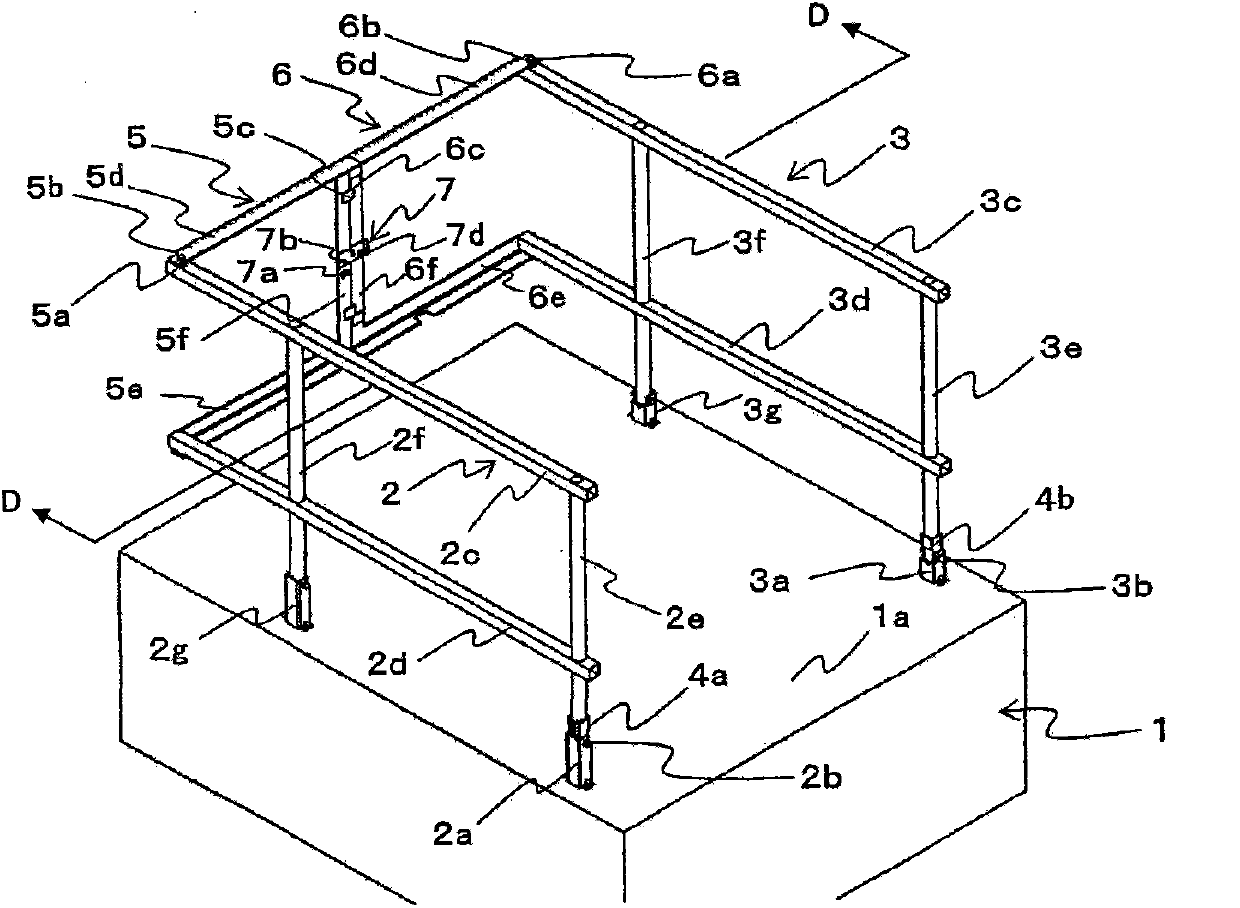
[0029] Such as figure 1 As shown, the handrail device for an elevator car according to this embodiment includes a left handrail 2 erected on the left side viewed from the landing side of the elevator, and a right handrail 3 erected on the right side viewed from the landing side. In addition, a rear armrest to be described later that connects the left armrest 2 and the right armrest 3 is included.

[0030] The left armrest 2 has, for example, a front vertical post 2e and a rear vertical post 2f, an upper stack 2c fixed to the front vertical post 2e and the rear vertical post 2f and disposed on the upper side, and a stack disposed on the lower side of the upper stack 2c. Middle stack 2d. Similarly, the right armrest 3 also includes, for example, a front vertical post 3e and a rear vertical post 3f, an upper stack 3c fixed to t...


PUM


Abstract

The invention provides an armrest device in an elevator car which is installed on the upper of the elevator car without needing insert operation of a pin, and an arranging method. The device comprises a left armrest (2), a right armrest (3) and a back armrest, wherein the back armrest is composed of a left back armrest (5) and a right back armrest (6). A left armrest limiting part of the invention for limiting the rotation of the left armrest is composed of a left armrest turning prevention part (4a), which is inserted into a left connection part (2a) of the upper (1a) of the elevator car (1), is accepted between front vertical columns (2e) of the left armrest of the left connection part, and can make the left armrest slide downwards because of gravity when standing. In addition, A right armrest limiting part for limiting the rotation of the right armrest is composed of a right armrest turning prevention part (4b), which is inserted into a right connection part (3a) of the upper of the elevator car, is accepted between front vertical columns (3e) of the right armrest of the right connection part, and can make the right armrest slide downwards because of gravity when standing.

Description

technical field [0001] The invention relates to an elevator car upper handrail device and an elevator car upper handrail setting method which can be kept in an upright setting state on the upper part of the elevator car. Background technique [0002] When inspecting equipment and the like in the lift path of the elevator, maintenance workers often climb on the upper part of the elevator car to perform work. Therefore, a handrail, that is, a car upper handrail device, is provided on the upper part of the elevator car to ensure the safety of the maintenance worker when working. [0003] As such prior art, there is an upper handrail device for an elevator car as shown in Patent Document 1. As shown in FIG. This prior art includes: a left handrail erected on the left side viewed from the landing side of the elevator, a right handrail erected on the right side viewed from the landing side, and a rear handrail connecting the left handrail and the right handrail. In addition, thi...

Claims


Application Information

Patent Timeline
Patent Type & Authority Applications(China)
IPC IPC(8): B66B11/02
Inventor 渡边隆行山崎雅宏佐佐木悟岛田胜博大菅麻里高木俊彰
Owner HITACHI BUILDING SYST CO LTD
Learn More