
Slurry shaker mixer

A mixer and slurry technology, which is applied in the directions of shaking/oscillating/vibrating mixers, mixers, dissolving, etc., can solve the problems such as prolonging the stirring time, stirring the jelly-like slurry that does not meet the technological standards, and low efficiency. Production efficiency, not easy to delaminate, and the effect of eliminating blind spots

Active Publication Date: 2015-10-14
EGING PHOTOVOLTAIC TECHNOLOGY CO LTD
View PDF6 Cites 0 Cited by
  • Summary
  • Abstract
  • Description
  • Claims
  • Application Information

AI Technical Summary

Problems solved by technology

[0004] The technical problem to be solved by the present invention is: in order to solve the problem that the traditional mixer stirs the slurry, the jelly-like slurry cannot reach the process standard, the stirring time is prolonged, and the efficiency is low. The present invention provides a slurry shaking mixer to solve the above-mentioned question

Method used


Image

  • Slurry shaker mixer
  • Slurry shaker mixer
  • Slurry shaker mixer

Examples


Embodiment Construction

[0017] The present invention is described in further detail now in conjunction with accompanying drawing. These drawings are all simplified schematic diagrams, which only illustrate the basic structure of the present invention in a schematic manner, so they only show the configurations related to the present invention.

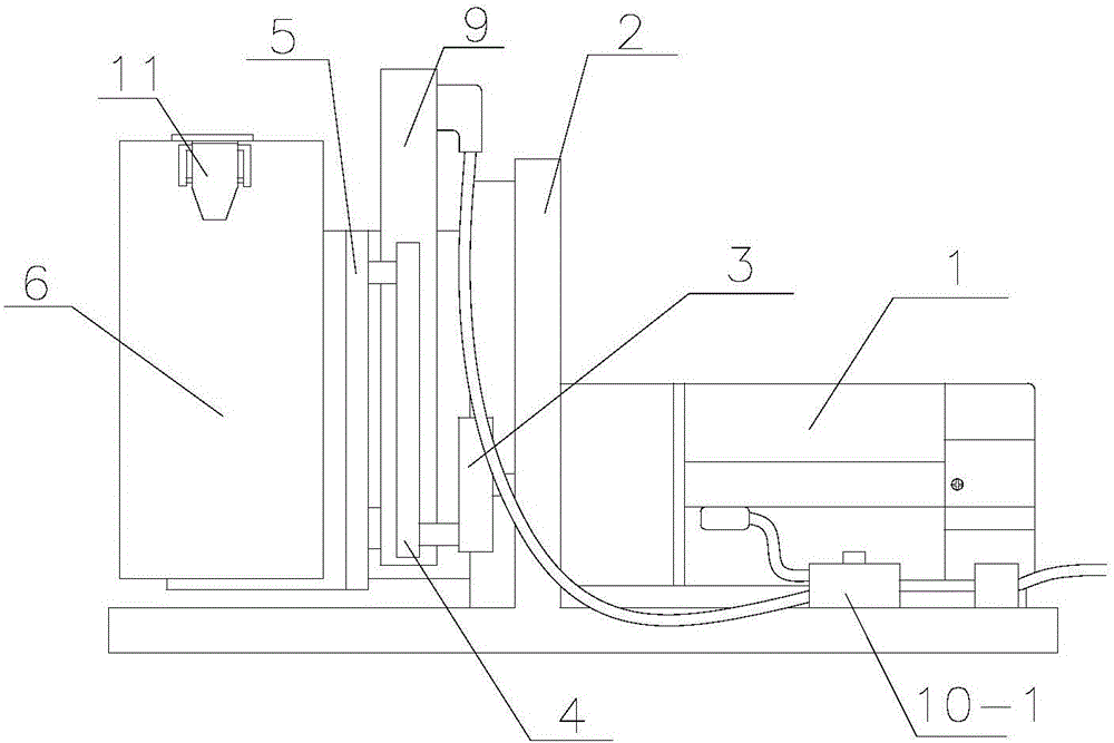
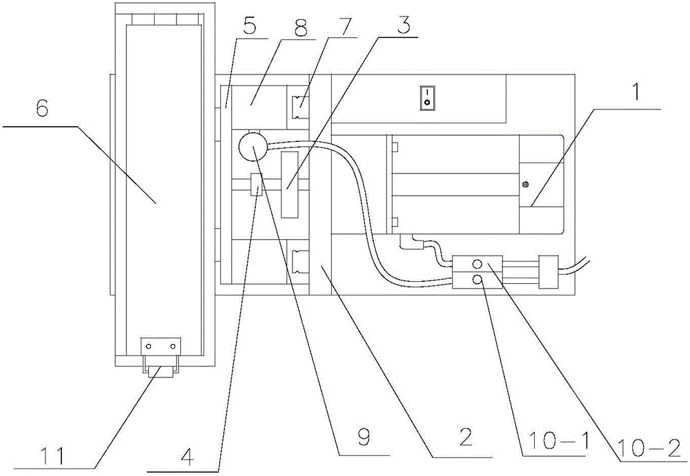
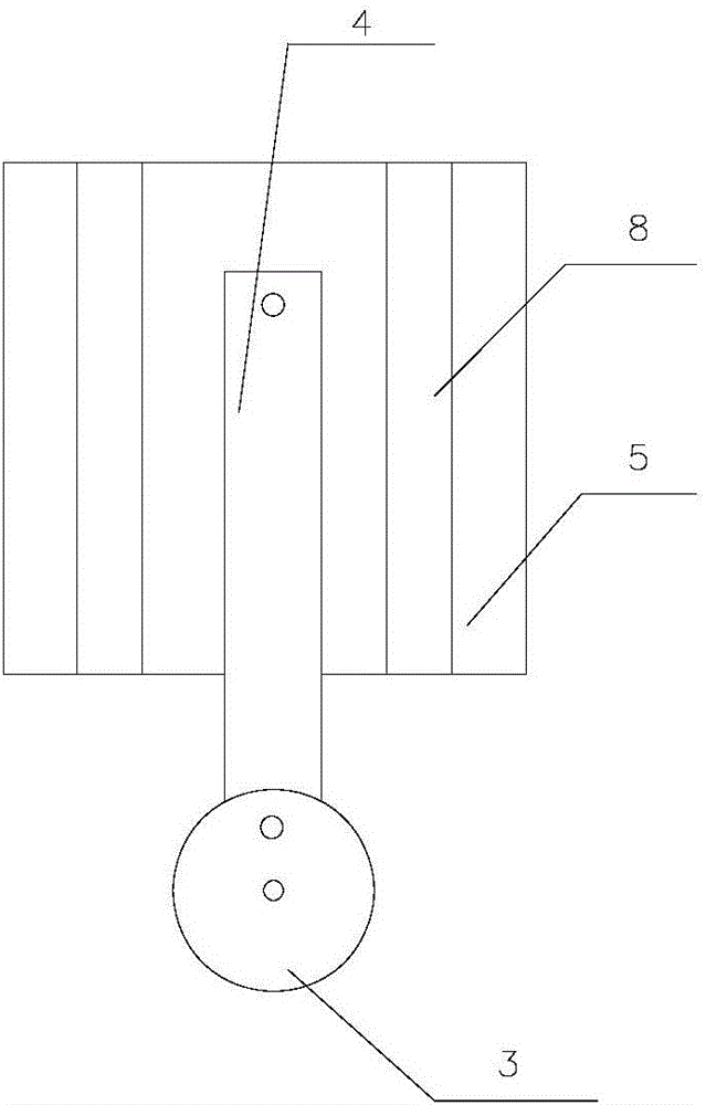
[0018] Such as Figure 1-3 As shown, the slurry vibrating mixer of the present invention includes a motor 1, a support plate 2, a motor disc 3, a rotating connecting rod 4, a fixed plate 5 and a shelving box 6 for placing a slurry bucket, and the output shaft of the motor 1 is facing the The support plate 2, the output shaft of the motor 1 passes through the support plate 2 and is connected to the center of the motor disk 3, the edge of the motor disk 3 is hinged with one end of the rotating link 4, and the other end of the rotating link 4 is hinged with the fixed plate 5 , the fixed plate 5 is fixedly connected with the storage box 6, the two sides of the su...


PUM


Abstract

The invention relates to a slurry shaking stirrer which comprises a motor, a supporting plate, a motor disc, a rotating connecting rod, a fixing plate and a containing box. An output shaft of the motor penetrates through the fixing plate and is in transmission connection with the circle center of the motor disc. The edge part of the motor disc is hinged to one end of the rotating connecting rod. The other end of the rotating connecting rod is hinged to the fixing plate which is fixedly connected with the containing box. Guiding tracks which are parallel to each other and are perpendicular to a horizontal line are arranged on the two sides of the supporting plate. Sliding blocks are arranged on the guiding tracks and are fixedly connected with the fixing plate. According to the slurry shaking stirrer, the motor is used for driving the motor disc to drive the rotating connecting rod to move, so that the containing box moves up and down, a slurry barrel in the containing box shakes up and down along with the containing box, jelly-shaped slurry in the slurry barrel can become even and cannot be layered easily during shaking, the blind zone of slurry stirring of a traditional stirrer is removed, and meanwhile stirring time is shortened, the slurry which meets the production technology requirements is obtained by stirring, and production efficiency is improved.

Description

technical field [0001] The invention relates to a mixer, in particular to a slurry shaking mixer. Background technique [0002] At present, most of the slurry mixing still adopts the traditional mechanical stirring method, but when dealing with a jelly-like slurry, use a traditional mixer to stir the slurry, the slurry is still jelly-like, and it is prone to blind spots that cannot be stirred. The slurry is easy to stratify, the stirred slurry cannot meet the technical requirements, and the slurry in the blind area is easy to waste. [0003] Therefore, many manufacturers usually use longer stirring time to change the status quo, which is inefficient and affects production efficiency. Contents of the invention [0004] The technical problem to be solved by the present invention is: in order to solve the problem that the traditional mixer stirs the slurry, the jelly-like slurry cannot reach the process standard, the stirring time is prolonged, and the efficiency is low. The...

Claims


Application Information

Patent Timeline
Patent Type & Authority Patents(China)
IPC IPC(8): B01F11/00
Inventor 王少华
Owner EGING PHOTOVOLTAIC TECHNOLOGY CO LTD
Learn More