Electric motor drive

A driving device and motor technology, applied in the direction of electromechanical devices, electric components, and control/drive circuits, etc., to achieve the effect of firm fixation, compact motor drive device, and low cost

Active Publication Date: 2013-11-27
ROBERT BOSCH GMBH
View PDF5 Cites 2 Cited by
  • Summary
  • Abstract
  • Description
  • Claims
  • Application Information

AI Technical Summary

Problems solved by technology

[0003] A disadvantage of the prior art is that, for example, the plugs of different motor drives have to be arranged and / or fixed differently for the application at different plug positions on the motor drive

Method used


Image

  • Electric motor drive
  • Electric motor drive
  • Electric motor drive

Examples


Embodiment Construction

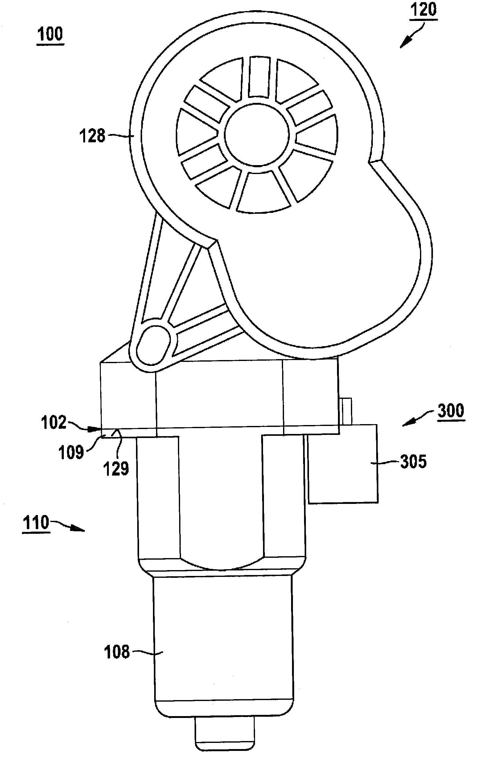
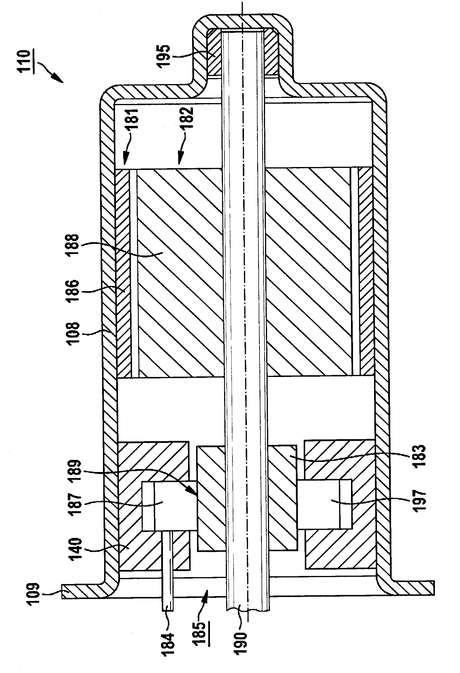
[0036] figure 1 According to one specific embodiment, an electric motor drive 100 is shown with an electric motor 110 and a transmission 120 drivable by the electric motor, which can be used, for example, as a window lifter, a seat adjustment device and / or in a motor vehicle. Drive unit for windshield wipers. The electric motor 110 is shown equipped with a motor housing 108 having a fixing flange 109 . The transmission 120 is equipped, for example, with a transmission housing 128 which has a fastening section 129 .

[0037] According to one embodiment, the fastening flange 109 of the motor housing 108 is fastened to the fastening section 129 of the transmission housing 128 , for example screwed, riveted, welded, glued or fixed in any other manner. Section 129 on. In this case, the motor housing 108 and the transmission housing 128 form an interface 102 with one another at the transition, at which interface the two housings 108 , 128 bear against each other.

[0038] As sho...


PUM


Abstract

The invention relates to an electric motor drive comprising an electric motor (100) and a transmission (120), which can be driven by said electric motor and is disposed in a transmission housing (128). The electric motor (110) has an associated motor housing (108) and can be connected in an electrically conducting manner to an associated power source via contact elements located on an associated brush holder and via a plug (305) so as to be powered. The plug (305) is associated with a plug module (305), at least some sections of which are disposed in the region of an interface (102) formed between the motor housing (108) and the transmission housing (128). The plug module (300) and the brush holder are designed as separate components.

Description

technical field [0001] The invention relates to an electric motor drive with an electric motor and a transmission driveable by the electric motor, the transmission being arranged in a transmission housing, wherein the electric motor has an associated motor housing and is arranged in an associated The contact elements and plugs on the brush holder can be electrically conductively connected to an associated current source in order to supply current. Background technique [0002] Such electric motor drives are known from the prior art, which can be used, for example in the automotive industry, for driving seat adjustment devices, window lifters and / or windscreen wipers in vehicles . The electric motor drive has an electric motor arranged in a motor housing which is operatively connected to a gear arranged in a gear housing, wherein the motor housing and the gear housing are fastened to each other, for example screwed together Join or rivet. The electric motor can be supplied...

Claims


Application Information

Patent Timeline
Patent Type & Authority Applications(China)
IPC IPC(8): H02K7/116
CPCH02K11/0015H02K11/0084H02K5/225H02K11/21H02K11/38
Inventor C·鲍尔M·米利T·霍尔策
Owner ROBERT BOSCH GMBH
Why Eureka
Try Eureka