
oled illuminants for lamps

A technology for luminous bodies and lamps, which is applied to semiconductor devices, light sources, electric light sources, etc. of light-emitting elements, which can solve the problems of no contact protection and achieve the effects of reducing costs and improving contact protection

Inactive Publication Date: 2016-10-19
PANASONIC CORP +2
View PDF10 Cites 2 Cited by
  • Summary
  • Abstract
  • Description
  • Claims
  • Application Information

AI Technical Summary

Problems solved by technology

No contact protection is provided for said conductive parts

Method used


Image

  • oled illuminants for lamps
  • oled illuminants for lamps
  • oled illuminants for lamps

Examples


Embodiment Construction

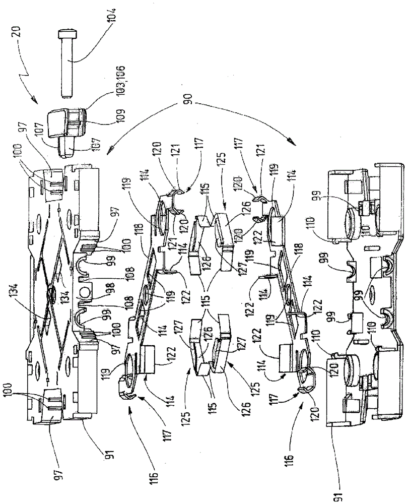
[0036] figure 1 A block diagram-like schematic diagram is shown of a luminaire 15 which is connected via a supply line 16 to a voltage source 17 . The voltage source 17 provides a DC voltage for supplying the lamp 15 . A ballast can be used as voltage source 17, for example. It is only indicated that there is a switch 18 in the supply line 16 here, which is used to switch the lamp 15 on or off. Instead of the voltage source 17 , a current source 17 ′ can also be used, as schematically indicated by the dotted line. The current source 17' can be an integral part of a ballast. The current source 17 ′ can also be arranged as a current driver inside the lampholder 20 and can be connected to a common voltage network. The lamp holder 20 is preferably connected in series to the current source 17'.

[0037] The lamp 15 has at least one socket 20 . in accordance with figure 1 In the case of the embodiment, a plurality of lamp holders 20 are provided, and they are arranged in a ma...


PUM


Abstract

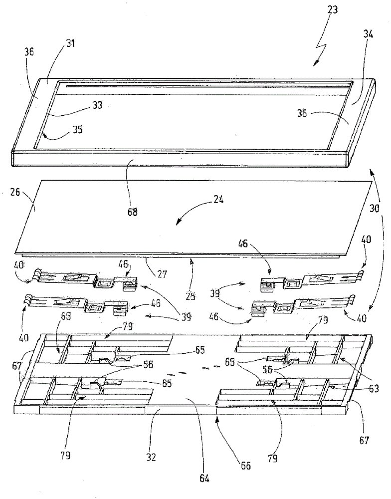
The invention relates to a luminaire (23) and a lamp holder (20) for a lamp (15). The features of the lamp holder ( 20 ) can also be implemented independently of the features of the light ( 23 ). The illuminant ( 23 ) has a preferably planar luminous surface ( 24 ). One or more semiconductor light emitting elements are arranged in the light housing (30). The illuminant connection ( 70 ) required for the mechanical and electrical connection to the lampholder ( 20 ) is arranged on the rear side ( 66 ) of the illuminant ( 23 ) opposite the luminous area ( 24 ). The dimensions of the illuminant ( 23 ) are preferably larger than the dimensions of the lampholder ( 20 ), so that the illuminant ( 23 ) completely covers the lampholder ( 20 ) when viewed in a direction perpendicular to the luminous surface ( 24 ) of the illuminant. A particularly aesthetically pleasing impression can thereby be achieved. A large total luminous area of ​​the luminaire ( 15 ) with an aesthetically pleasing overall image can be realized particularly easily in a modular manner by means of the lampholder ( 20 ) and the illuminant ( 23 ).

Description

technical field [0001] The invention relates to a luminaire having semiconductor light-emitting elements, such as light-emitting diodes (LEDs) and in particular organic light-emitting diodes (OLEDs). The illuminant is designed as a planar illuminant. There is an increasing demand for flat lamps. Such flat luminaires are installed for lighting, for example on walls or roofs, and are notable for their luminous properties and visually appealing overall impression on the one hand and their extremely low energy consumption on the other hand. Background technique [0002] Luminaires consisting of OLED illuminants and lamp holders are known in the prior art. For example, DE 603 ​​06 720 T2 discloses an organic light-emitting diode layer arranged on a substrate. The base plate is designed as a plate and has a tongue with a printed circuit on a narrow side. By means of the tongue, the base plate can be inserted into a corresponding insertion opening of a lampholder and contacted ...

Claims


Application Information

Patent Timeline
Patent Type & Authority Patents(China)
IPC IPC(8): F21K9/00F21S2/00F21V21/02F21V23/06F21S8/00F21S8/04F21Y115/10F21Y115/15
CPCF21K9/00F21S2/005F21S8/033F21S8/04F21V21/02F21V23/06F21Y2105/00F21Y2115/10F21Y2115/15Y02B20/30F21V21/002
Inventor U.施平特格K.迪克曼B.格茨S.罗斯巴赫T.芒特斯V.J.J.范蒙特福特
Owner PANASONIC CORP
Learn More