
Explosion-proof and intrinsically safe type control box for mine

An intrinsically safe control box technology, applied in the direction of electrical equipment shells/cabinets/drawers, electrical components, etc., can solve problems such as large volume, affecting the layout of box door components, and heavy quality

Active Publication Date: 2013-11-27
上海大柏树防爆技术有限公司
View PDF4 Cites 2 Cited by
  • Summary
  • Abstract
  • Description
  • Claims
  • Application Information

AI Technical Summary

Problems solved by technology

[0003] Existing mine explosion-proof and intrinsically safe control equipment is composed of two independent boxes, which have the defects of large volume and heavy weight. Moreover, the explosion-proof box and the intrinsically safe box both use hinged single doors, and the wiring The board is fixed in the narrow box, the connection between the display screen, speaker, microphone and control buttons on the box door and many components on the circuit board in the box, and the connection between the components on the circuit board in the box There are many wires, and there are more than 150 inter-internal patch wires, which is extremely inconvenient for installation, debugging, and maintenance
In addition, in the existing mining explosion-proof and intrinsically safe control equipment, the locks of the intrinsically safe box are directly installed on the box door, which will occupy the limited space of the box door and affect the layout of many devices on the box door

Method used


Image

  • Explosion-proof and intrinsically safe type control box for mine
  • Explosion-proof and intrinsically safe type control box for mine
  • Explosion-proof and intrinsically safe type control box for mine

Examples


Embodiment Construction

[0022] The embodiments of the present invention will be described in further detail below in conjunction with the accompanying drawings, but the present embodiments are not intended to limit the present invention, and any similar structures and similar changes of the present invention should be included in the protection scope of the present invention.

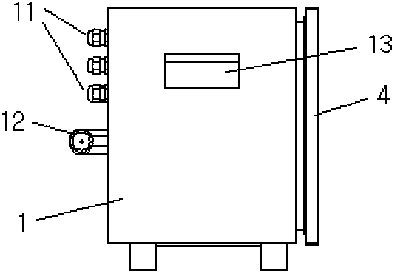
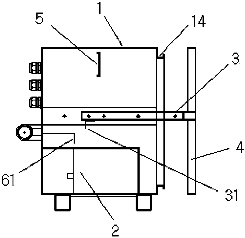
[0023] Such as Figure 1-Figure 5 As shown, a mine explosion-proof and intrinsically safe control box provided by the embodiment of the present invention includes a box body 1 open to the front on one side, and a box panel 4 for closing the front opening of the box body;

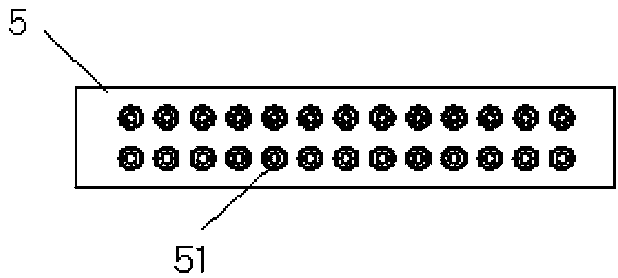
[0024] It is characterized in that: the inner cavity of the box body 1 is provided with a main board bracket 3 capable of sliding back and forth, and a guide rail for guiding the sliding of the main board bracket, and a wire passing beam 5 is fixed at the middle and upper part of the inner cavity of the box body, The lower part of the box cavity is provided ...


PUM


Abstract

The invention discloses an explosion-proof and intrinsically safe type control box for mine, relates to the technical field of mine equipment, and aims at solving the technical problem that existing equipment can not be used for detection conveniently. A main plate bracket capable of sliding forward and backward is arranged in a box body of the control box. A wire passing beam is fixed on the middle upper portion of the inner cavity of the box body. An explosion-proof cavity is formed in the lower portion. A main circuit board is arranged on the main board bracket. An intrinsically safe power supply is arranged in the explosion-proof cavity. A lockset and a wire inlet array are arranged on the back box wall of the box body. An wire passing hole array is arranged on the wire passing beam. A lock catch is fixed at the back end of the main board bracket. A lock hole of the lock set is backward exposed out of the back surface of the box body. A lock cylinder of the lockset extends forwards into the inner cavity of the box body and is fixedly provided with a lock hook. A waterproof groove is formed in a front opening in the front end of the box body. A box panel is fixed at the front end of the main board bracket. Input cables and output cables on the main circuit board respectively penetrate through various wire passing holes and various wire inlet holes and then are connected to the outside of the box body. The control box is used for mine electrical equipment power supply control.

Description

technical field [0001] The invention relates to mine equipment technology, in particular to a mine explosion-proof and intrinsically safe control box technology. Background technique [0002] The existing mine explosion-proof and intrinsically safe control equipment is mainly composed of an intrinsically safe box and an explosion-proof box. The intrinsically safe box is stacked above and below the explosion-proof box, and a combined device is formed through connection. The explosion-proof box is equipped with an intrinsically safe power supply, and the door panel of the intrinsically safe box is equipped with a display screen, a loudspeaker, a microphone and control buttons, and a control circuit is installed inside the intrinsically safe box. [0003] Existing mine explosion-proof and intrinsically safe control equipment is composed of two independent boxes, which have the defects of large volume and heavy weight. Moreover, the explosion-proof box and the intrinsically safe...

Claims


Application Information

Patent Timeline
IPC IPC(8): H05K5/00
Inventor 廖米和宋秋萍付瑾瑾
Owner 上海大柏树防爆技术有限公司
Learn More