
Computer lockset device

A technology of computer locks and shackles, applied to devices for locking portable objects, building locks, lock applications, etc., can solve problems such as troublesome use, space occupation, and unsightly appearance, and achieve convenience in use and aesthetic enhancement Effect

Inactive Publication Date: 2008-02-27
MIZ ENGINEERING LIMITED
View PDF0 Cites 7 Cited by
  • Summary
  • Abstract
  • Description
  • Claims
  • Application Information

AI Technical Summary

Problems solved by technology

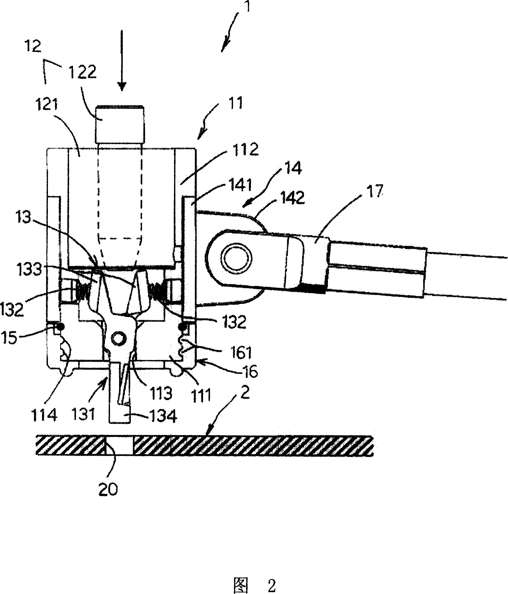
However, when the lock needs to be locked after unlocking, the tubular key 10 must be removed before the lock bar 122 can be pushed. It will be a little troublesome to use
Simultaneously, because the lock bar 122 protrudes from the lock body 121, in addition to taking up space, it is also less attractive in appearance.

Method used


Image

  • Computer lockset device
  • Computer lockset device
  • Computer lockset device

Examples


Embodiment Construction

[0023] As shown in FIGS. 4 and 5 , the preferred embodiment of the computer lock device of the present invention is suitable for locking a computer 3 with a lock hole 31 . The computer 3 may be a notebook computer, but may also be a desktop computer mainframe, a computer screen, a printer, a scanner, a projector and other related computer peripherals. The computer lock device includes a lock case unit 4 , a lock unit 5 , a head unit 6 , and a chain unit 7 .

[0024] The lock housing unit 4 has a circular housing base 41 , a collar 42 sleeved on the outer peripheral surface of the circular housing base 41 , a limiting ring 43 , and a bottom housing base 44 . The shell seat 41 has a base wall 411 defining a through hole 410 , and a surrounding wall 412 extending outward from the outer periphery of the base wall 411 . Three circles of annular grooves 413 spaced up and down are formed on the peripheral surface of the base wall 411 . Two opposite accommodating holes 414 are forme...


PUM


Abstract

The present invention discloses one kind of computer lock device including one lock shell unit, one lock buckle unit, one lock head unit and one lock chain unit. The lock shell unit has one circular seat and one ring on the seat; the lock buckle unit has two cross oscillating hooks in a through hole and one elastic piece to make the hooks close each other; the lock head unit has one lock body fixed inside the circular seat and one lock core rod capable of turning between one locking position and one unlocking position; and the lock core rod has its end stretched beyond the lock body and defining one long shaft and one short shaft. In the unlocking position, the lock core rod has its end separated from two lock hooks; while in the locking position, the lock core rod end pushes these lock hooks outwards for separating. The computer lock device has convenient use and good look.

Description

technical field [0001] The invention relates to a lock device. Background technique [0002] In recent years, many computer manufacturers often participate in computer product exhibitions held in various countries to showcase their own developed products, thereby opening up international sales. However, for computers or peripheral hardware such as notebook computers, computer hosts, LCD screens, scanners, or printers, which are relatively high-priced commodities, in order to prevent commodities from being stolen in the exhibition hall, manufacturers often use computer Special locks lock these commodities. [0003] As shown in Figures 1 and 2, the common computer lock device 1 is a product developed by the applicant before, and can be locked on the lock hole 20 of the notebook computer 2. The lock device 1 includes a lock cylinder 11, which is fixed on the The lock head 12 in the lock cylinder 11, the locking unit 13 arranged at the bottom of the lock cylinder 11 to buckle ...

Claims


Application Information

Patent Timeline
Patent Type & Authority Applications(China)
IPC IPC(8): E05B73/00
Inventor 吕建志
Owner MIZ ENGINEERING LIMITED
Learn More