
A method of in-phase power supply for an electrified railway and its standby structure

A technology of electrified railway and same-phase power supply, which is applied in the direction of electrical components, power lines, circuit devices, etc., can solve the problems of low harmonic content and large traction power, and achieve the effects of advanced technology, improved economy, and avoided expansion of faults

Active Publication Date: 2016-05-18
CHINA RAILWAYS CORPORATION +1
View PDF6 Cites 0 Cited by
  • Summary
  • Abstract
  • Description
  • Claims
  • Application Information

AI Technical Summary

Problems solved by technology

[0003] High-speed and heavy-duty railways have widely used high-power AC-DC electric locomotives or EMUs based on full-control devices such as IGBTs and IGCTs. The core is traction converters with multiple sets of four-quadrant PWM control and multiple control. The content is small and the power factor is close to 1, but the traction power of AC-DC electric locomotives or EMUs is large. For example, the rated power of single-vehicle high-speed EMUs running in large formations can reach 25MW (equivalent to 5 trains on ordinary speed railways). The power quality problems caused by high-power single-phase loads on the three-phase grid, mainly caused by three-phase voltage unbalance (negative sequence), are becoming more and more serious, and must be paid attention to

Method used


Image

  • A method of in-phase power supply for an electrified railway and its standby structure
  • A method of in-phase power supply for an electrified railway and its standby structure

Examples


Embodiment

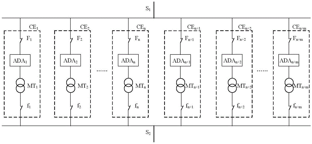
[0026] Such as figure 1 As shown in the figure, a structure of the same-phase power supply equipment for electrified railways includes incoming line S1, n+m groups of parallel-connected in-phase power supply units, outgoing line S2, and measurement and control unit CU; the same-phase power supply unit CE k AC-DC-AC Converter ADA k , matching transformer MT k and distribution switch F k , f k Connected in series; AC-DC-AC converter ADA k , matching transformer MT k and distribution switch F k , f k Both are single-phase structures; the measurement and control unit CU is connected to the power distribution switch F k , f k The control terminal, AC-DC-AC converter ADA k The measurement and control terminal is also connected to the upper level control system; k=1,2,...,n+m.

[0027] Common phase power supply unit CE k AC-DC-AC Converter ADA in k It is composed of a rated module and a redundant module. The rated module and the redundant module work together. The number ...


PUM


Abstract

The invention discloses an electrified railway in-phase power supplying method and a standby structure. The standby structure mainly comprises feeding wires and n+m sets of in-phase power supplying units and wire discharging and detecting units, wherein the n+m sets of in-phase power supplying units and wire discharging and detecting units are connected in parallel; each in-phase power supplying unit is composed of an alternating-direct-alternating converter, a matching transformer and a distribution switch, wherein the alternating-direct-alternating converter, the matching transformer and the distribution switch are connected in series and each in-phase power supplying unit is of a single-phase structure; the number n of the working in-phase power supplying units is determined by the in-phase power compensation capacity needed by traction substation and the rated capacity of each set of in-phase power supplying unit; the number m of the standby in-phase power supplying units is the minimum value satisfying the reliability requirements; due to the redundancy of an internal module of each alternating-direct-alternating converter, when one alternating-direct-alternating converter breaks down but the corresponding in-phase power supplying unit does not break down, one standby in-phase power supplying unit is used so that smooth transition of one working unit and one standby unit can be achieved, therefore, state repair of the in-phase power supplying units is achieved, fault enlargement is avoided, and the reliability of the system is improved. The two wires are used for serving as mutually standby power substations so that feeding wire switching can be achieved, the feeding wires can share the same set of in-phase power supplying unit, and the economical efficiency of the system can be greatly improved. The standby structure is advanced and reliable in technology and easy to achieve.

Description

technical field [0001] The invention relates to the field of AC electrified railway power supply, in particular to a structure of an electrified railway in-phase power supply equipment. Background technique [0002] Electrified railways generally adopt the single-phase power frequency AC system powered by the public power system. In order to distribute the single-phase traction load as evenly as possible in the three-phase power system, the electrified railway often adopts the scheme of alternating phase sequence and separate phase and partition power supply. The adjacent power supply areas at the phase-splitting partitions are divided by phase-splitting insulators to form electrical split phases, also known as phase splits. In order to prevent electric locomotives from burning catenary suspension components due to electric phase splitting due to electric phase separation, and even causing phase-to-phase short-circuit and other accidents, as the train speed continues to incr...

Claims


Application Information

Patent Timeline
Patent Type & Authority Patents(China)
IPC IPC(8): H02J9/06B60M3/00
CPCY02B70/30Y04S20/20
Inventor 李群湛郭锴解绍锋舒泽亮郭育华李亚楠贺建闽李子晗赵元哲余俊祥
Owner CHINA RAILWAYS CORPORATION
Learn More