
Lead screw guiding device

A guide device and lead screw technology, applied in the direction of measuring devices, instruments, scientific instruments, etc., can solve the problems of inaccurate positioning and guidance, complex guide device structure, difficulty in meeting the coaxiality requirements of the force axis and the host axis, and achieve Simple structure, friction reduction effect

Inactive Publication Date: 2013-11-27
JINAN KEHUI TESTING INSTR
View PDF8 Cites 3 Cited by
  • Summary
  • Abstract
  • Description
  • Claims
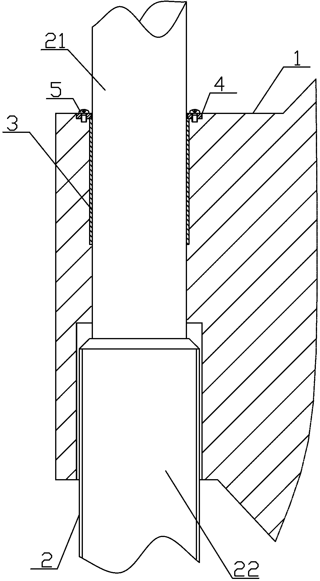
  • Application Information

AI Technical Summary

Problems solved by technology

This kind of guide device has complex structure and inaccurate positioning and guidance, and it is difficult to meet the coaxiality requirements of the force axis of the sample and the axis of the host during the test.

Method used


Image

  • Lead screw guiding device

Examples


Embodiment Construction

[0009] Such as figure 1 As shown, the screw guiding device of the present invention includes an upper beam 1 and a screw 2. The screw 2 includes a positioning shaft part 21 and a threaded part 22 of the screw. The guide positioning hole, the positioning shaft part 21 is arranged in the guide positioning hole, the inner upper end of the guide positioning hole is provided with a bearing hole, the self-lubricating bearing 3 is installed in the described bearing hole, and the upper end of the self-lubricating bearing 3 is provided with Bearing end cover 4, said bearing end cover 4 is fixedly connected with upper beam 1 by screws 5.

[0010] During the process of the upper beam moving up and down along the positioning shaft, the inner hole of the self-lubricating bearing is always in contact with the outer circumference of the positioning shaft, which ensures that the upper beam always moves along the axis of the screw and satisfies the stress on the sample during the test. The co...


PUM


Abstract

The invention discloses a lead screw guiding device used on a testing machine. The lead screw guiding device comprises an upper cross beam and a lead screw; the lead screw comprises a lead screw thread part and a positioning shaft part; the lead screw guiding device is characterized in that a guiding positioning hole matched with the positioning shaft part is formed in the upper cross beam; the positioning shaft part is arranged in the guiding positioning hole; a bearing hole is formed in the inner upper end of the guiding positioning hole; a self-lubricating bearing is mounted in the bearing hole; a bearing end cover is arranged at the upper end of the self-lubricating bearing; the bearing end cover is fixedly connected with the upper cross beam through bolts. The lead screw guiding device is simple in structure; the arrangement of the self-lubricating bearing ensures the accuracy in positioning and guiding of the lead screw, so that the coaxiality requirement of a stress axis and a host axis during the testing process of a sample can be met, and simultaneously, the friction received by the upper cross beam during the up and down movement process can be reduced.

Description

technical field [0001] The invention relates to a screw guiding device, in particular to a screw guiding device used on a testing machine. Background technique [0002] In a broad sense, a testing machine is an instrument that verifies the quality or performance of a product or material according to the design requirements before it is put into use. Testing machines are widely used in various industries. At present, the screw used for transmission and loading in the testing machine is guided by arranging guide wheels on the upper beam. This kind of guiding device has complex structure and inaccurate positioning and guiding, and it is difficult to meet the coaxiality requirements of the force axis of the sample and the axis of the host machine during the test. Contents of the invention [0003] In order to solve the above problems, the present invention provides a lead screw guide device, which can ensure the accuracy of the positioning and guidance of the lead screw, and ...

Claims


Application Information

Patent Timeline
IPC IPC(8): G01N3/02
Inventor 姜德志
Owner JINAN KEHUI TESTING INSTR
Learn More