
A Combined Die and Its Application in Forming Composite Structural Parts

A technology of combining molds and composite materials, applied in the field of composite material molding, can solve the problems of high expansion pressure, multi-cavity side by side, and excessive cavity space.

Active Publication Date: 2016-05-04
AEROSPACE RES INST OF MATERIAL & PROCESSING TECH +1
View PDF3 Cites 0 Cited by
  • Summary
  • Abstract
  • Description
  • Claims
  • Application Information

AI Technical Summary

Problems solved by technology

[0003] In the molding process of multi-cavity structure products, there are problems such as too large cavity space and multiple cavities side by side. The existing silicone rubber soft mold has problems such as excessive expansion pressure and uneven pressure transmission. Simply modify the silicone rubber soft mold. Dimensions can no longer be obtained to meet the dimensional accuracy required by the drawings

Method used


Image

  • A Combined Die and Its Application in Forming Composite Structural Parts
  • A Combined Die and Its Application in Forming Composite Structural Parts
  • A Combined Die and Its Application in Forming Composite Structural Parts

Examples


Embodiment 1

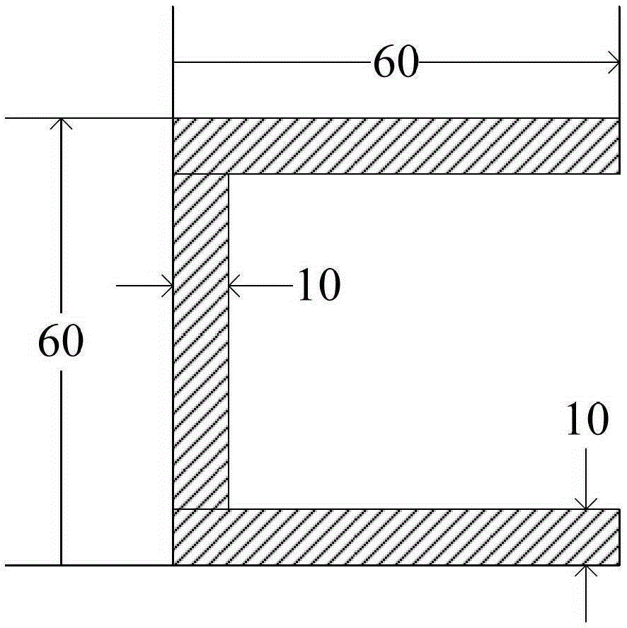
[0025] The cross-section of the product to be formed is inverted U-shaped, with a width of 60mm, a height of 60mm, and a thickness of 10mm; image 3 Shown:

[0026] 1) Make a silicone rubber / metal core combination soft mold that is consistent with the shape of the pressurized cavity of the product to be formed; make a closed metal female mold that is consistent with the shape of the product to be formed;

[0027] 2) Lay composite material on the outside of the soft mold made in step 1). After the layup is completed, put it into the closed metal female mold, and fix the metal core and the closed metal female mold with screws; heat, shape composite materials;

[0028] 3) Demoulding: first open the closed metal female mold, and then take the soft mold out of the cavity of the product to obtain the molded composite structural part.

[0029] The silicone rubber in the silicone rubber / metal core combined soft mold described in the above step 1) is an addition type room temperature...

Embodiment 2

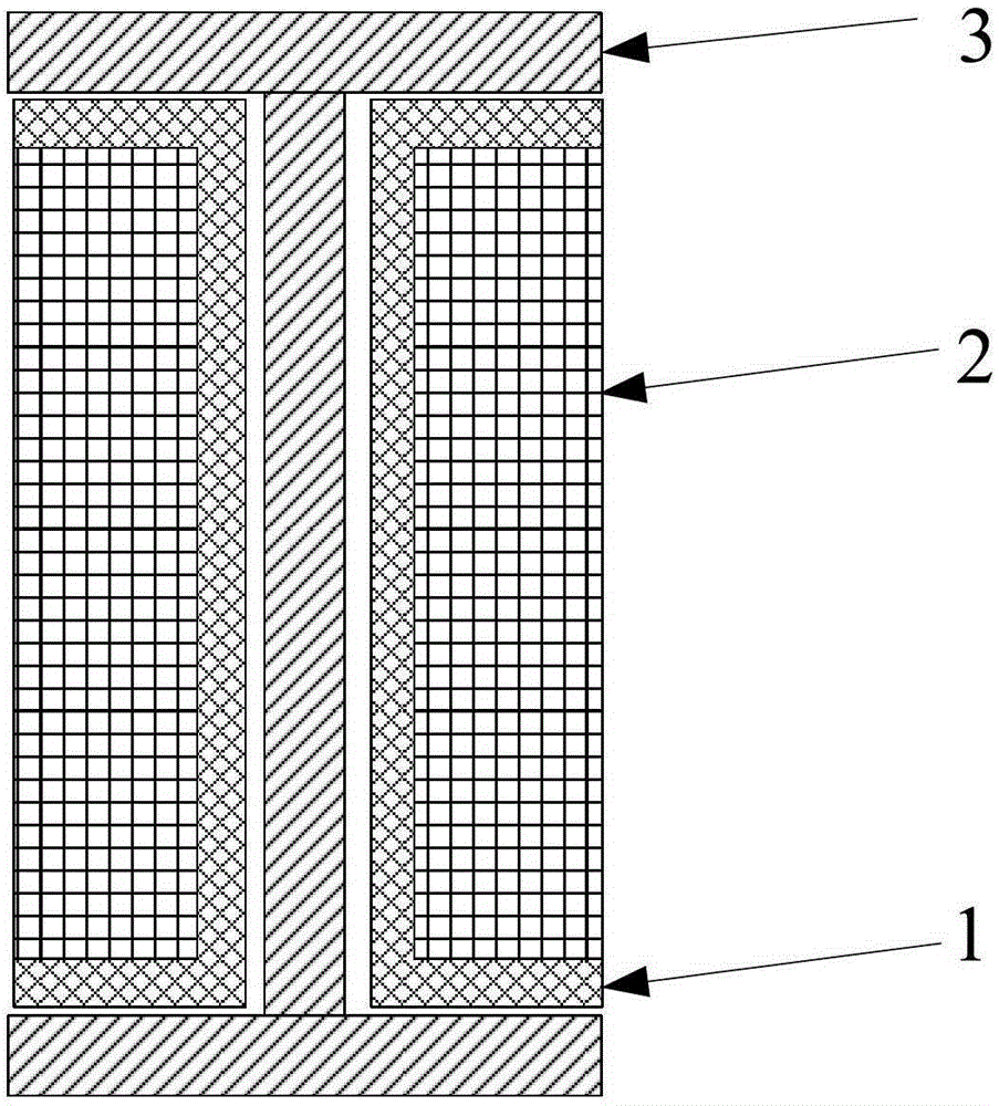
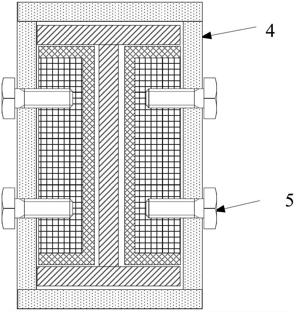
[0031] like figure 1 and figure 2 As shown, a combination mold includes a silicone rubber / metal core composite soft mold, a closed metal female mold 4 and a connector 5; the silicone rubber / metal core composite soft mold includes a silicone rubber 1 and a metal core 2 The periphery of the metal core 2 is silicone rubber 1, and the silicone rubber / metal core combined soft mold mold is installed in the cavity of the product 3 to be formed; the closed metal female mold 4 is located outside the product 3 to be formed; the closed metal female mold 4 and the metal core 2 are fixedly connected by screws 5;

[0032] The cross-section of the product to be formed is I-shaped, with a width of 60mm, a height of 60mm, and a thickness of 10mm; Figure 4 Shown:

[0033] 1) Make a silicone rubber / metal core combination soft mold that is consistent with the shape of the pressurized cavity of the product to be formed; make a closed metal female mold that is consistent with the shape of the ...


PUM


Abstract

The invention relates to a combined die and its application in molding a composite material structure member, and belongs to the technical field of composite material molding. The combined die comprises silicon rubber (1), a metal core (2), a closed metal female die (4) and a connecting piece (5); the closed metal female die (4) is positioned outside a product for molding (3); and the closed metal female die (4) is fixedly connected with the metal core (2) through the connecting piece (5). The product molded through using the silicon rubber / metal core combined flexible die has an obvious better appearance than products molded through complete silicon rubber flexible dies; and the product having an appearance quality and an internal quality which satisfy requirements is obtained through adjusting the volume ratio of the silicon rubber flexible die to the metal core. The adjustment of the ratio of the volume of the silicon rubber flexible die to the volume of the metal core is realized.

Description

technical field [0001] The invention relates to a composite mold and its application in molding composite material structural parts, belonging to the technical field of composite material molding. Background technique [0002] Resin-based composite silicone rubber soft mold molding process: Silicone rubber soft mold molding process uses silicone rubber soft mold as the core mold, rigid material (metal) as the negative mold, and resin-based composite material (made of prepreg layer) Placed between the core mold and the female mold, when the mold is heated, because the volume expansion of the silicone rubber core mold (silicone rubber heat expansion) is limited by the composite material and the metal female mold, a huge expansion pressure will be generated, so as to achieve heat curing. The curing pressure is applied to the composite material during the process. No external pressure source is required during the molding process, and it is suitable for overall co-curing of com...

Claims


Application Information

Patent Timeline
Patent Type & Authority Patents(China)
IPC IPC(8): B29C33/00B29C70/30B29C70/54
Inventor 谭朝元邓火英梁馨谭珏林治峰宋朝晖秦德辉孙宝岗凌英董波蒋文革冷霜刘宏涛林琳王保林姜琦
Owner AEROSPACE RES INST OF MATERIAL & PROCESSING TECH
Learn More