High-efficiency mine tailing metal concentrating machine

A tailings, high-efficiency technology, applied in the direction of solid separation, classification, chemical instruments and methods, etc., can solve the problems of inconvenient installation and maintenance, poor selection effect, increased production costs, etc., to improve machine utilization and reduce production costs , Easy installation and maintenance

Inactive Publication Date: 2013-11-27
彭建家
View PDF8 Cites 1 Cited by
  • Summary
  • Abstract
  • Description
  • Claims
  • Application Information

AI Technical Summary

Problems solved by technology

[0003] Most of the existing concentrators have complex mechanical structures, inconvenient installation and maintenance, and the grade of ore to be selected is relatively fixed, so it is impossible to apply one machine to a wider range, which virtually increases the production cost, and the beneficiation effect is poor. fragile parts

Method used


Image

  • High-efficiency mine tailing metal concentrating machine
  • High-efficiency mine tailing metal concentrating machine

Examples


Embodiment 1

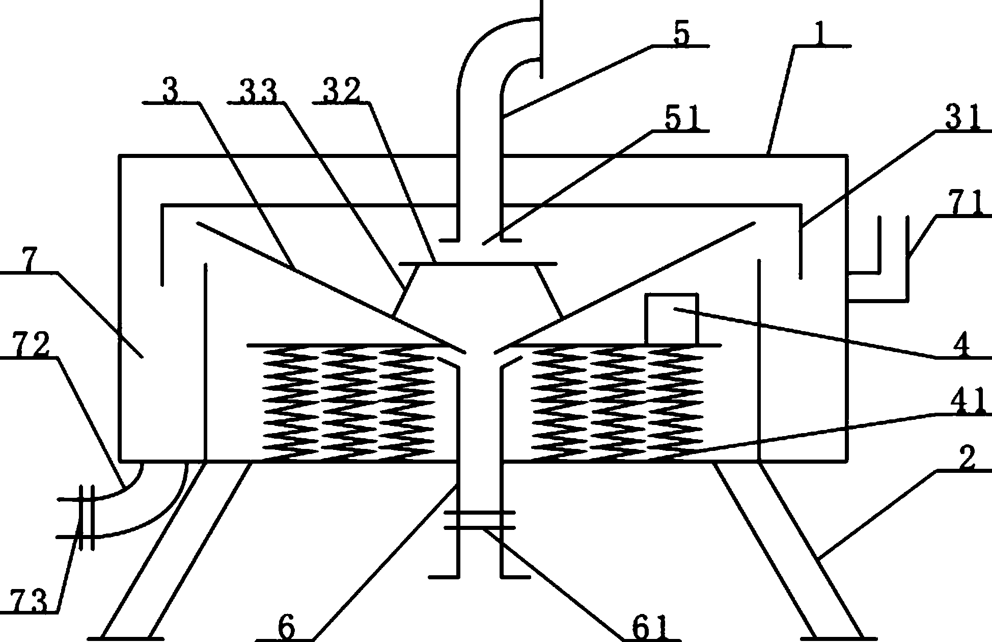
[0021] like figure 1 , a high-efficiency tailings metal enrichment machine, including a casing 1, a frame 2, a hopper 3, a vibrator 4 and an annular waste sand tank 7, the casing 1 is cylindrical, and the top center of the casing 1 is provided with an ore inlet pipe 5. The ore discharge pipe 6 is set at the bottom of the casing 1, and an annular waste sand tank 7 is arranged inside the casing 1 along the wall of the casing 1, and the annular waste sand tank 7 is provided with a water adding pipe 71 and a sand discharge pipe 72;

[0022] The upper part of the distribution hopper 3 is provided with a bucket cover 31, and there is a gap between the bucket cover 31 and the distribution hopper 3. The aforementioned ore feeding pipe 5 passes through the casing 1 and the bucket cover 31 and communicates with the distribution hopper 3. Inside the distribution hopper 3 A mine-blocking plate 32 opposite to the mouth of the ore feeding pipe 5 is set, and the bottom of the mine-blocking p...

Embodiment 2

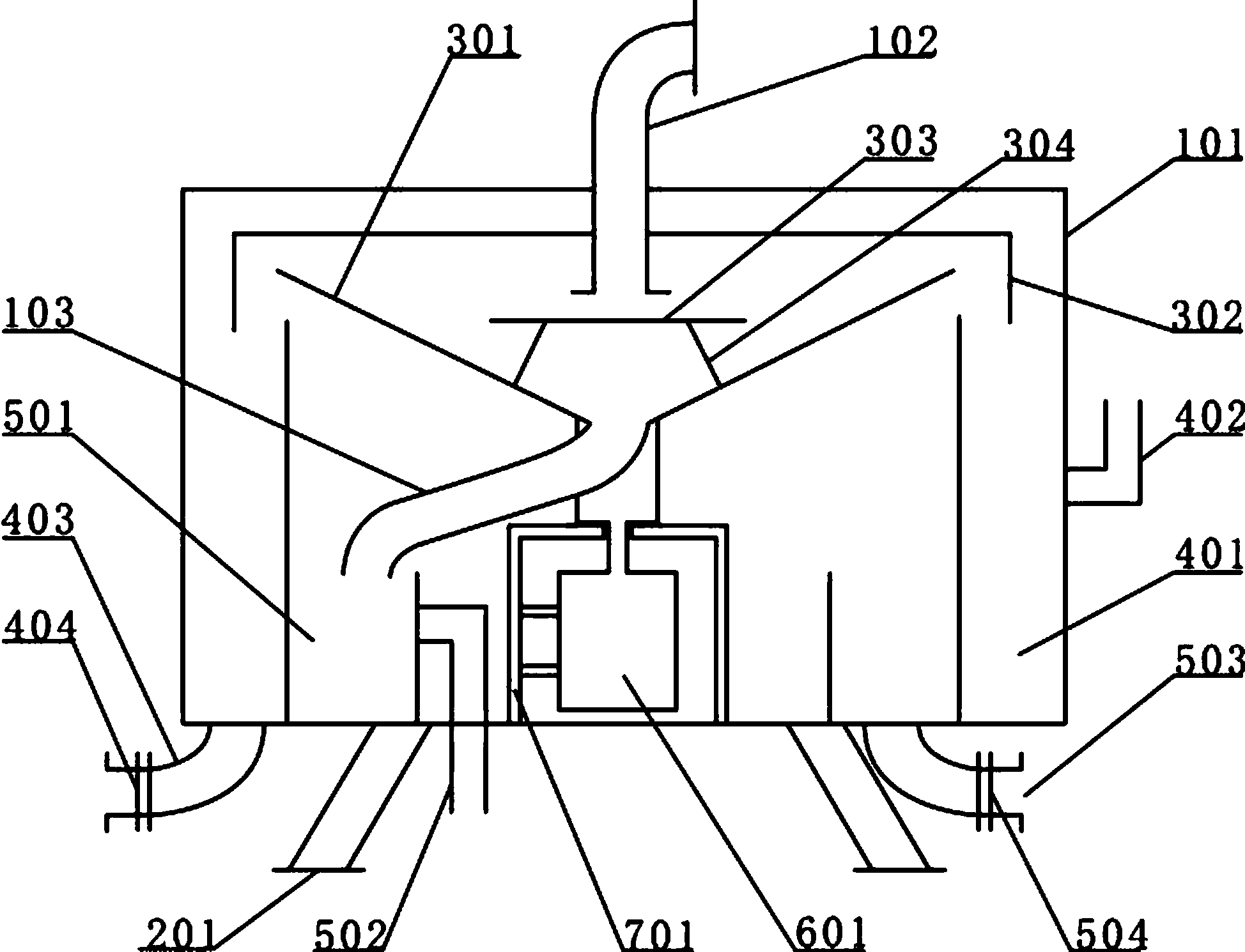
[0026] like figure 2 ,, high-efficiency tailings metal enrichment machine, including a casing 101, a frame 201, a hopper 301, a motor 601, an annular waste sand tank 401 and a concentrate tank 501, the casing 101 is cylindrical, and the top of the casing 101 An ore inlet pipe 102 is arranged in the center, an ore outlet pipe 503 is arranged at the bottom of the casing 101, an annular waste sand tank 401 is arranged inside the casing 101 along the wall of the casing 101, and the annular waste sand tank 401 is provided with a water adding pipe 402 and a sand discharge pipe 403;

[0027] The upper part of the sub-hopper 301 is provided with a bucket cover 302, and there is a gap between the bucket cover 302 and the sub-hopper 301. The aforementioned ore feeding pipe 102 passes through the casing 101 and the bucket cover 302 and communicates with the sub-hopper 301. Inside the sub-hopper 301 A mineral blocking plate 303 opposite to the mouth of the ore feeding pipe 102 is provide...


PUM


Abstract

The invention relates to a mine tailing concentrating recovery device, in particular to a high-efficiency mine tailing metal concentrating machine. The high-efficiency mine tailing metal concentrating machine comprises a machine shell, a machine frame, a distribution hopper and a concentrating device, wherein the machine frame is fixed at the bottom of the machine shell, the machine shell is cylindrical, an annular waste sand groove is formed in the machine shell and provided with a water adding pipe and a water draining pipe, the distribution hoper is communicated with an ore inlet pipe, the bottom of the distribution hopper is connected with the concentrating device, and the concentrating device is of a vibration type or a rotary type. According to the high-efficiency mine tailing metal concentrating machine, different concentrating rates can be achieved by regulating the working frequency of the concentrating device according to requirements. Besides, the high-efficiency mine tailing metal concentrating machine is simple in structure, not prone to being damaged, and beneficial to improving mine tailing concentrating efficiency and quality.

Description

technical field [0001] The invention relates to the beneficiation of metal or non-metal tailings, in particular to a high-efficiency tailings metal enrichment machine with adjustable beneficiation grade. Background technique [0002] The distribution of some low-grade ores in my country is very wide, and a large amount exists in mines and tailings. Due to the high cost of ore dressing, its mining and utilization value is extremely low. In response to this situation, in order to effectively develop and utilize low-grade ores, the market mainly enriches low-grade ores into high-grade ores through various concentrators. [0003] Most of the existing concentrators have complex mechanical structures, inconvenient installation and maintenance, and the grade of ore to be selected is relatively fixed, so it is impossible to apply one machine to a wider range, which virtually increases the production cost, and the beneficiation effect is poor. Parts are fragile. Contents of the in...

Claims


Application Information

Patent Timeline
Patent Type & Authority Applications(China)
IPC IPC(8): B07B13/10
Inventor 彭建家
Owner 彭建家
Why Eureka
Try Eureka