
Binocular vision navigation system and method based on inspection robot in transformer substation

An inspection robot and binocular vision technology, applied in the field of binocular vision navigation system, can solve the problems such as the inability to plan the walking path of the substation inspection robot, the inability to effectively avoid obstacles, and the error of obstacle detection.

Active Publication Date: 2013-11-20
STATE GRID INTELLIGENCE TECH CO LTD
View PDF3 Cites 80 Cited by
  • Summary
  • Abstract
  • Description
  • Claims
  • Application Information

AI Technical Summary

Problems solved by technology

[0005] (1) During the driving process of the substation inspection robot, there are many devices on both sides of the driving path, resulting in complex image backgrounds, resulting in overlapping of obstacles and equipment areas, which brings great difficulties to target extraction and segmentation;
[0006] (2) Road area information will be affected by outdoor lighting changes, special weather, etc., causing interference information on the road surface, which is easy to introduce obstacle detection errors;
[0007] (3) In the existing technology, the walking path of the substation inspection robot is often unable to be specifically planned, and obstacles cannot be effectively avoided

Method used


Image

  • Binocular vision navigation system and method based on inspection robot in transformer substation
  • Binocular vision navigation system and method based on inspection robot in transformer substation
  • Binocular vision navigation system and method based on inspection robot in transformer substation

Examples


Embodiment Construction

[0062] The present invention will be further described below in conjunction with the accompanying drawings and embodiments.

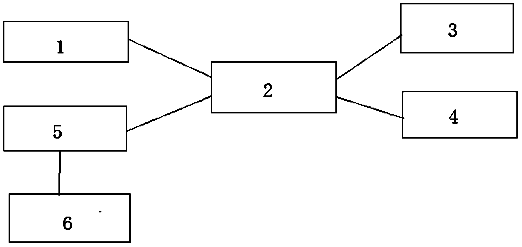
[0063] like figure 1 As shown, a binocular vision navigation system based on substation inspection robot, which includes a robot body, and an image acquisition system 1 for collecting environmental information maps on the road ahead is provided at the end of the forearm of the robot body;

[0064] Image acquisition system 1: Image acquisition system 1 collects environmental images on the road ahead of the robot, and then uploads the collected images to visual analysis system 3 through network transmission system 2. Image acquisition system 1 includes binocular cameras, and binocular cameras pass through the transmission line Connect to the image acquisition card, and then connect to the network transmission system 2 by wire;

[0065] The network transmission system 2 includes a wireless network bridge, a wireless router, and a receiver, and transmits t...


PUM


Abstract

The invention discloses a binocular vision navigation system based on an inspection robot in a transformer substation. The binocular vision navigation system comprises a robot body, an image collecting system, a network transmission system, a vision analysis system, a route planning system and a robot control system, wherein the image collecting system is arranged in front of the robot body and used for collecting environmental information images of a forwarding road and then uploads the environmental information images to the vision analysis system on the basis of the network transmission system; the vision analysis system detects a barrier in the road area of the transformer substation according to binocular image information collected by the image collecting system and inside and outside parameters of a camera; the route planning system plans a route according to environment information detected by the vision system and timely adjusts the walking routes of the robot, so that the robot can be prevented from being collided with the barrier; and the robot control system controls moving of the robot body according to the route planned by the route planning system. The invention simultaneously discloses a vision navigation method. By means of the system and the method, the self-adaptation ability of the robot to the environment is improved, the autonomous navigation function of the electric robot is really realized in the complicated outdoor environment, and the flexibility and the safety of the robot are improved.

Description

technical field [0001] The invention relates to a binocular vision navigation system and method, in particular to a binocular vision navigation system and method based on a substation inspection robot. Background technique [0002] With the development of sensor technology and processor technology, robot technology is developing towards an increasingly intelligent direction. The formation and development of computer vision theory has enabled robots to have a visual system similar to human binoculars, allowing robots to obtain more environmental information based on the visual system. Visual navigation technology mainly includes monocular, binocular stereo vision, trinocular and multi-camera structures. Monocular vision mainly uses the image information collected by the camera to identify the signs in the structural scene, directly uses the image plane information to judge the scene, and also uses the method of motion-based three-dimensional information recovery to navigate ...

Claims


Application Information

Patent Timeline
Patent Type & Authority Applications(China)
IPC IPC(8): G06T7/00G05D1/02
Inventor 李丽王滨海王海鹏张晶晶肖鹏
Owner STATE GRID INTELLIGENCE TECH CO LTD
Learn More