
a line structure

A cable management structure and chain link technology, which is applied in the electronic field, can solve the problems of reducing the integration of cable layout and the large space occupied by X-shaped chain links, and achieve the effects of rational layout, avoiding potential safety hazards, and improving integration density

Active Publication Date: 2015-11-25
HUAWEI TECH CO LTD
View PDF3 Cites 0 Cited by
  • Summary
  • Abstract
  • Description
  • Claims
  • Application Information

AI Technical Summary

Problems solved by technology

The X-shaped chain link in this cable management structure takes up a lot of space, which reduces the integration of cable layout

Method used


Image

  • a line structure
  • a line structure
  • a line structure

Examples


Embodiment Construction

[0038] The following will clearly and completely describe the technical solutions in the embodiments of the application with reference to the drawings in the embodiments of the application. Apparently, the described embodiments are only some of the embodiments of the application, not all of them. Based on the embodiments in this application, all other embodiments obtained by persons of ordinary skill in the art without making creative efforts belong to the scope of protection of this application.

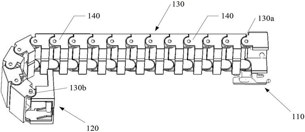
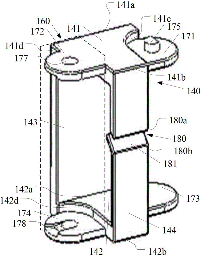
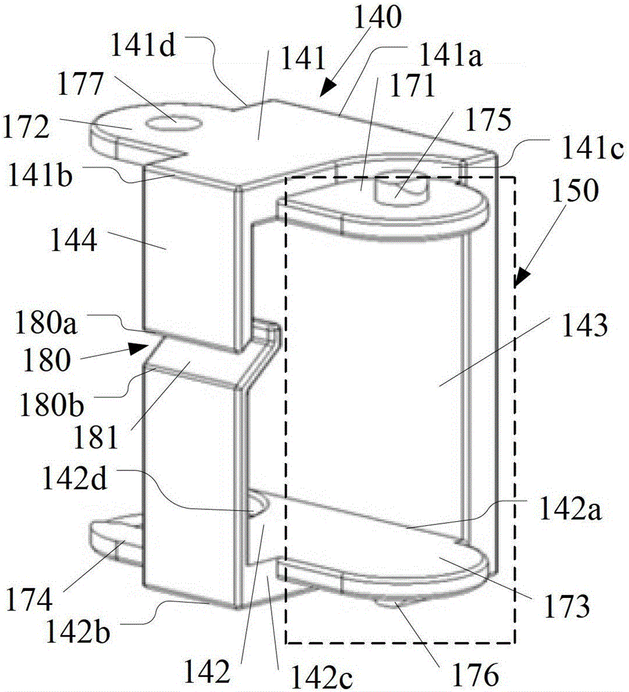
[0039] See Figure 1a to Figure 1g , Figure 1a A structural diagram of a line management structure provided by an embodiment of the present invention; Figure 1b Schematic diagram of the chain link structure provided by the embodiment of the present invention; Figure 1c Another visual structural schematic diagram of the chain link provided by the embodiment of the present invention; Figure 1d A schematic diagram of the cooperation of adjacent chain links provided by the embodim...


PUM


Abstract

The invention discloses a wire sorting structure which comprises a first fixed part, a second fixed part and a chain. The chain is formed by splicing at least two chain links, wherein each chain link is hollow, and the two sides of each chain link are open. One end of the first fixed part is connected with one end of the chain. One end of the second fixed part is connected with the other end of the chain. Moreover, the adjacent open sides of any two adjacent chain links are connected movably through a rotating shaft, therefore, the space occupied by the chain links is fully utilized, a cable can be accommodated in a hollow space formed by the chain, the integration density of a server is improved, the position of the cable is planned beneficially, and the potential safety hazard caused by contact and collision between the cable and other structures in the server is avoided. Back plates of every two adjacent chain links are located on the same side, therefore, the same sides of any two adjacent chain links on one side of the chain are connected seamlessly, the rotation angle of the two chain links is controlled to be limited within the range of 180 degrees, the two adjacent chain links are prevented from rotating disorderly, and the motion trail of the chain can be controlled.

Description

technical field [0001] The invention relates to the field of electronic technology, in particular to a wire management structure. Background technique [0002] In the implementation of server-related technologies, supporting hot swap is an important requirement for improving server performance. Hot-swapping is hot-swapping, and the function realized is to allow users to take out and replace damaged hardware devices such as hard disks, power supplies or boards without shutting down the system, interrupting business, and cutting off the power supply, thereby improving the system's reliability. The disaster recovery capability, scalability and flexibility can also reduce the impact of excessive starting current on hardware devices when switching on and off. Among them, in the hot-swapping technology, it is necessary to wrap or fix the cable through the cable management structure, so as to avoid the cable from being rubbed or collided with other objects during the hot-swapping ...

Claims


Application Information

Patent Timeline
Patent Type & Authority Patents(China)
IPC IPC(8): F16L3/01
Inventor 程经淦汪大林巫开俊
Owner HUAWEI TECH CO LTD
Learn More