Rotating shaft structure with touch switch

A technology of rotating shaft structure and touch switch, which is applied in the direction of pivot connection and other directions, and can solve problems such as inapplicability

Active Publication Date: 2015-06-10
JARLLYTEC CO LTD
View PDF4 Cites 0 Cited by
  • Summary
  • Abstract
  • Description
  • Claims
  • Application Information

AI Technical Summary

Problems solved by technology

Under such functional requirements, the known structure of the touch element will continue to rotate with the screen and thus is not applicable

Method used


Image

  • Rotating shaft structure with touch switch
  • Rotating shaft structure with touch switch
  • Rotating shaft structure with touch switch

Examples


Embodiment Construction

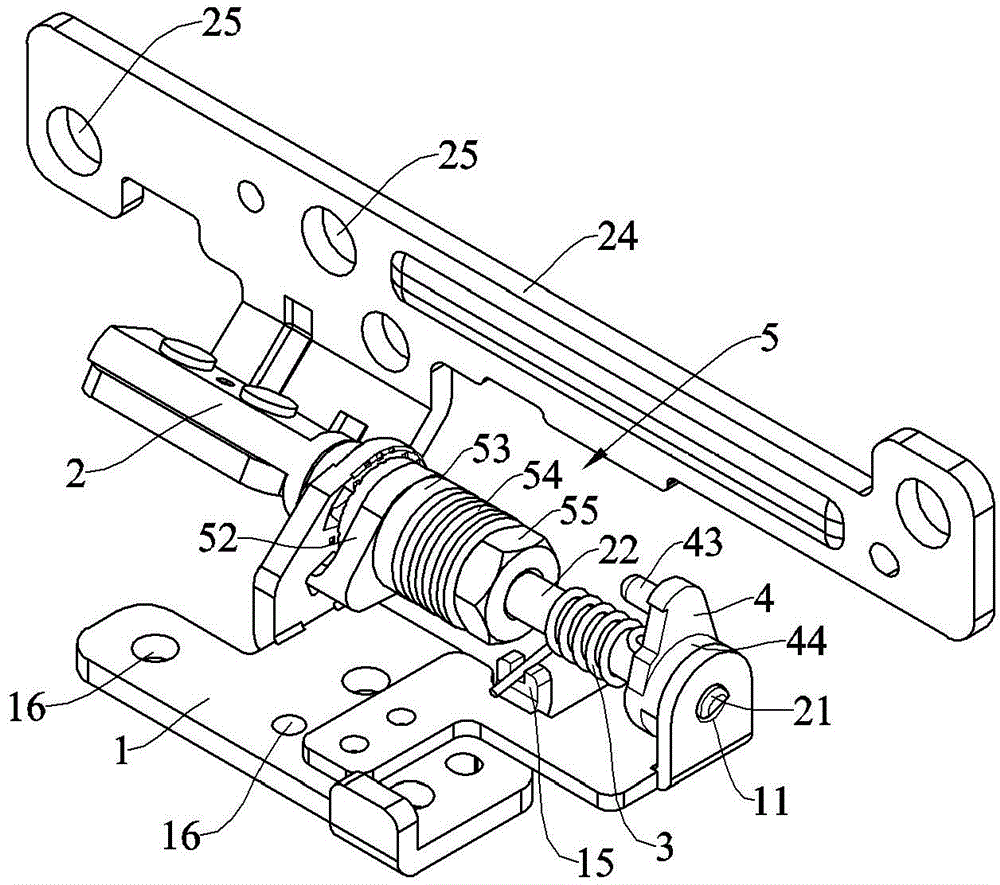
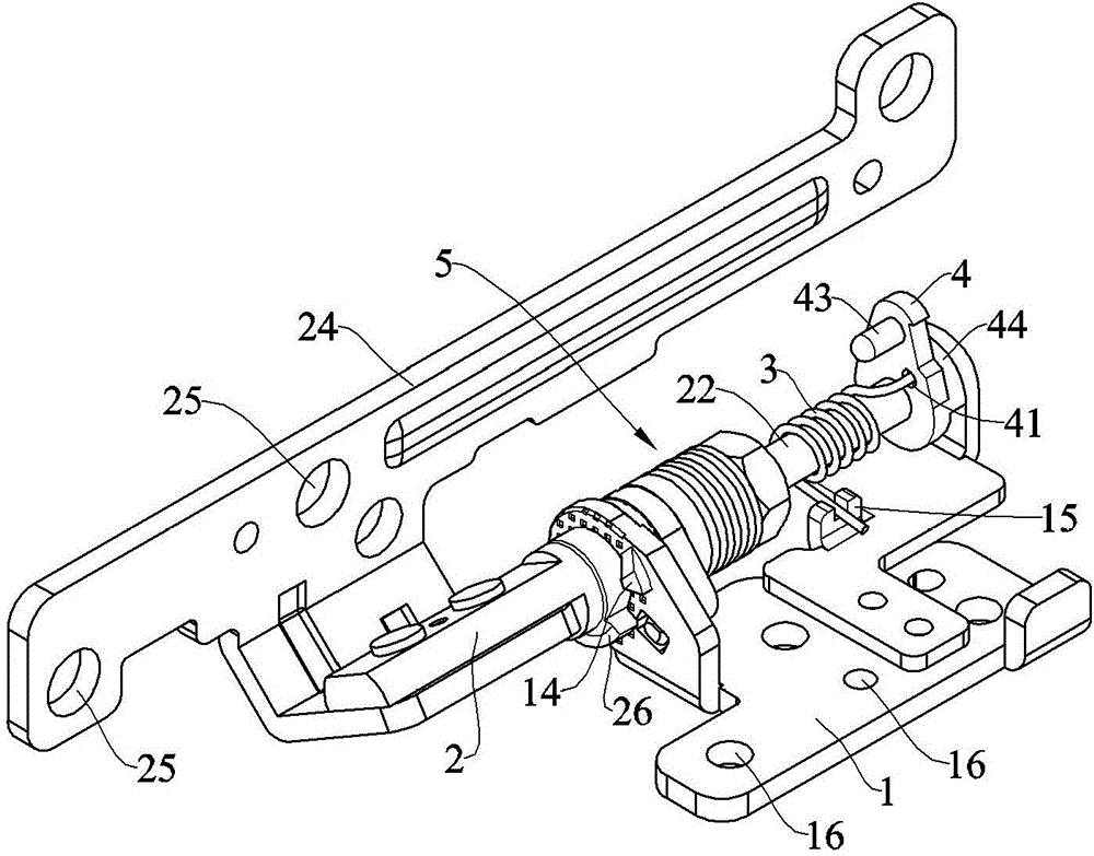
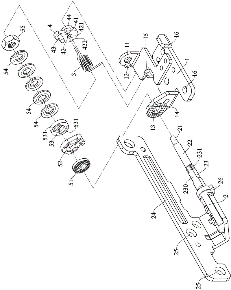
[0044] see Figure 1-4 , is an assembled perspective view, an assembled perspective view from another angle, an exploded assembly view, and an exploded assembly view from another angle of the present invention. The rotating shaft structure with a touch switch of the present invention includes a support frame 1 and a mandrel 2 passing through the support frame 1 . One end of the support frame 1 is provided with a vertical frame piece, and a circular first shaft hole 11 is provided on the frame piece, and a first stopper 12 protrudes from the side of the first shaft hole 11 . The other end of the support frame 1 is also provided with an upright frame piece. The frame piece is provided with a circular second shaft hole 13, and a second stopper 14 is protruded from the side of the second shaft hole 13. The support frame 1 is in the middle of the two frame pieces. A joint portion 15 is provided, and several fixing holes 16 are provided on the support frame 1 for fixing the support...


PUM


Abstract

The invention relates to a rotating shaft structure with a touch switch. The rotating shaft structure comprises a supporting frame, a mandrel and a touch piece. A non-circular first shaft section of the mandrel is sleeved by the touch piece via a limitation hole. The first shaft section can rotate for an angle range in the limitation hole and can be blocked at a first limitation side of the limitation hole. The touch piece is also provided with a convex part and a blocking part. The blocking part can rotate to block to a first block of the supporting frame, and after blocking, the first shaft section of the mandrel can continue to rotate in the limitation hole, so that the touch piece can open, with turning of a screen, to an angle, a dormancy state can be relieved, then the screen can continue to open but the touch piece may not be driven to rotate, and the problem of space limitation can be solved.

Description

technical field [0001] The invention relates to a rotating shaft structure with a touch switch, in particular to a rotating shaft structure capable of releasing the dormant state of a computer. Background technique [0002] When the computer is in hibernation mode, it saves all information in memory to the hard disk and then turns off the power to save power. If you want to restore the operation of the computer, press the power button, it will automatically load the information back to the memory, and restore the screen before the computer was turned off. [0003] The known notebook computer is equipped with a touch piece on the rotating shaft structure, and can automatically enter the sleep mode when the screen is rotated to a certain angle, as stated in the utility model patent "rotating shaft structure with automatic locking" of the applicant's Taiwan Announcement No. M296586 As shown, the rotating shaft structure also includes a touch piece 9, which is arranged between ...

Claims


Application Information

Patent Timeline
IPC IPC(8): F16C11/04F16C11/10
Inventor 张瑞鸿黄至忠吴重贤
Owner JARLLYTEC CO LTD
Why Eureka
Try Eureka