
Direct hydraulic turbine generator

A technology for hydroelectric generators and hydroturbines, applied to engine components, machines/engines, mechanical equipment, etc., can solve problems such as high cost, low power generation efficiency, and high manufacturing cost, and achieve reduced manufacturing costs, high power generation efficiency, and good operation effect of effect

Inactive Publication Date: 2013-11-13
CHONGQING TONGLI INDAL
View PDF6 Cites 3 Cited by
  • Summary
  • Abstract
  • Description
  • Claims
  • Application Information

AI Technical Summary

Problems solved by technology

[0002] Among the technologies using new energy, hydropower technology has received extensive attention. Its principle is to realize hydropower generation by doing work on water wheels through flowing water; generally including water wheels, hydroelectric generators, pumps, high-level water towers, charging The structure is relatively complex and the cost is very high; the construction of hydropower stations must also be carried out according to specific geographical conditions. Hydropower generation must build dams and have water flow drops. Hydropower generation must rely on large amounts of water resources, which must be changed and affected. A large number of water resources and ecological environment
The current hydro-generator drives the rotor of the generator through the water turbine. The structure is relatively complicated and a transmission device is required. Not only the manufacturing cost is high, but also the power generation efficiency is relatively low.

Method used


Image

  • Direct hydraulic turbine generator
  • Direct hydraulic turbine generator
  • Direct hydraulic turbine generator

Examples


Embodiment Construction

[0024] Hereinafter, the preferred embodiments of the present invention will be described in detail with reference to the accompanying drawings; it should be understood that the preferred embodiments are only for illustrating the present invention, not for limiting the protection scope of the present invention.

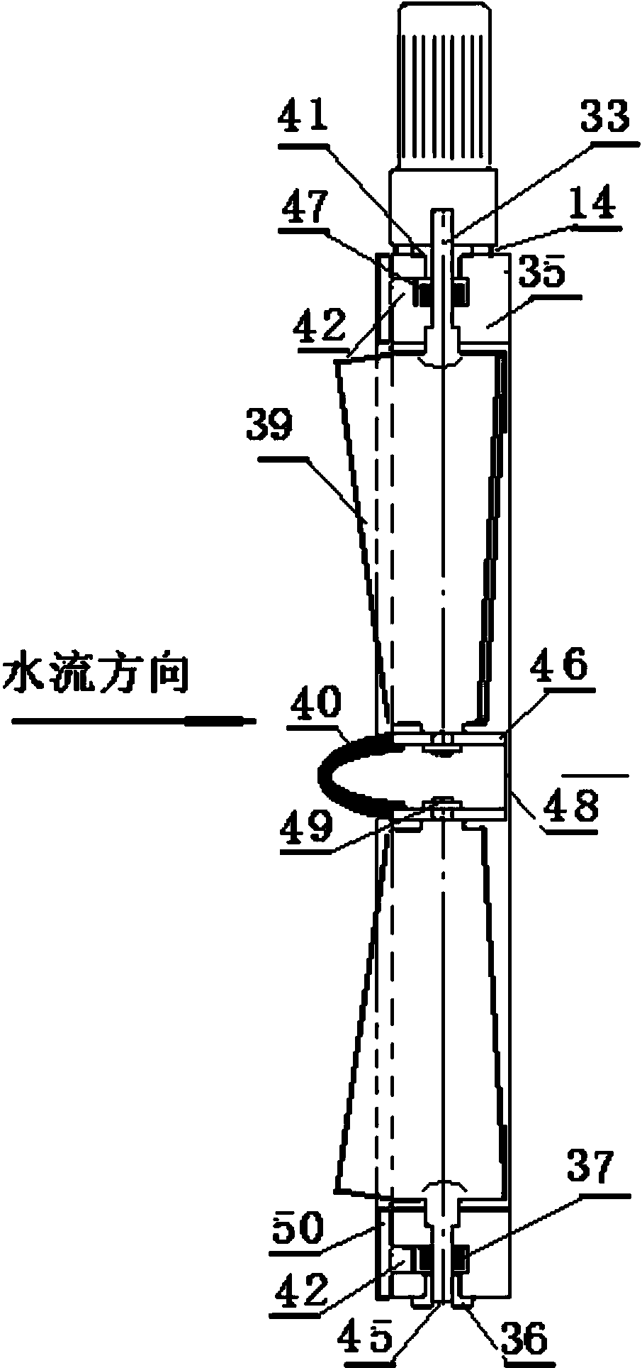
[0025] figure 1 Is a transverse cross-sectional view of a direct hydroelectric generator provided by an embodiment of the present invention, figure 2 Is a longitudinal cross-sectional view of a direct hydroelectric generator provided by an embodiment of the present invention, image 3 Is a longitudinal sectional view of a water guiding mechanism structure provided by an embodiment of the present invention, Figure 4 It is a transverse cross-sectional view of the water guiding mechanism structure provided by the embodiment of the present invention, as shown in the figure: the direct hydroelectric generator provided by the present invention includes a pipe, a water turbine a...


PUM


Abstract

The invention discloses a direct hydraulic turbine generator, which comprises a pipeline, a water turbine and a stator component, wherein the stator component is arranged on the inner wall of the pipeline, the water turbine is arranged in the inner cavity of the pipeline in the axial direction of the pipeline, the axial line of the water turbine is superposed with the axial line of the inner cavity of the pipeline, and a plurality of permanent magnets are uniformly distributed along the peripheral circumference of the water turbine, so that the stator component can cut magnetic induction lines of the permanent magnets when the water turbine rotates. According to the direct hydraulic turbine generator disclosed by the invention, the water turbine and a generator rotor are combined together, the structure becomes more compact, all transmission devices can be omitted, not only is the manufacturing cost greatly reduced, but also higher power generation efficiency can be obtained; a water guide mechanism is simpler in structure, the device needs to be wholly arranged in water, the whole device does not need to be sealed wholly, so the structure is compact. The direct hydraulic turbine generator is suitable for power generation in rivers, oceans and advective water environments, and the power generation efficiency is high.

Description

Technical field [0001] The invention relates to the field of hydroelectric generators, in particular to a direct hydroelectric generator. Background technique [0002] Among the technologies that adopt new energy, hydropower technology has received widespread attention. Its principle is to use flowing water to perform work on the water turbine to achieve hydropower generation; generally including water turbines, hydroelectric generators, pumps, high-level water towers, and charging Irrigation ports and electric energy management are composed of complex structures and very high costs; the construction of hydropower stations must also be carried out according to specific geographical conditions. Hydroelectric power generation must build dams and have water flow differences. Hydropower generation must rely on a large amount of water resources, which must be changed and affected. A lot of water resources and ecological environment. The current hydro-generator drives the generator ro...

Claims


Application Information

Patent Timeline
IPC IPC(8): F03B13/00
Inventor 沈家同
Owner CHONGQING TONGLI INDAL
Learn More