
Channel steel rail flash welding machine

A technology of trough rail and flash welding machine, which is applied in the direction of track, track laying, track maintenance, etc. It can solve the problems of increased welding resistance, sticking, troubles, etc., and achieves the elimination of opening and closing interference related to sticking and simple structure. Effect

Active Publication Date: 2013-11-13
CHANGZHOU RUITAI ENG MASCH CO LTD +1
View PDF9 Cites 3 Cited by
  • Summary
  • Abstract
  • Description
  • Claims
  • Application Information

AI Technical Summary

Problems solved by technology

A series of problems encountered when using the above-mentioned existing equipment for welding are: 1) The welding equipment must be turned around to weld the other side of the track, and the turning around is time-consuming, laborious and very troublesome
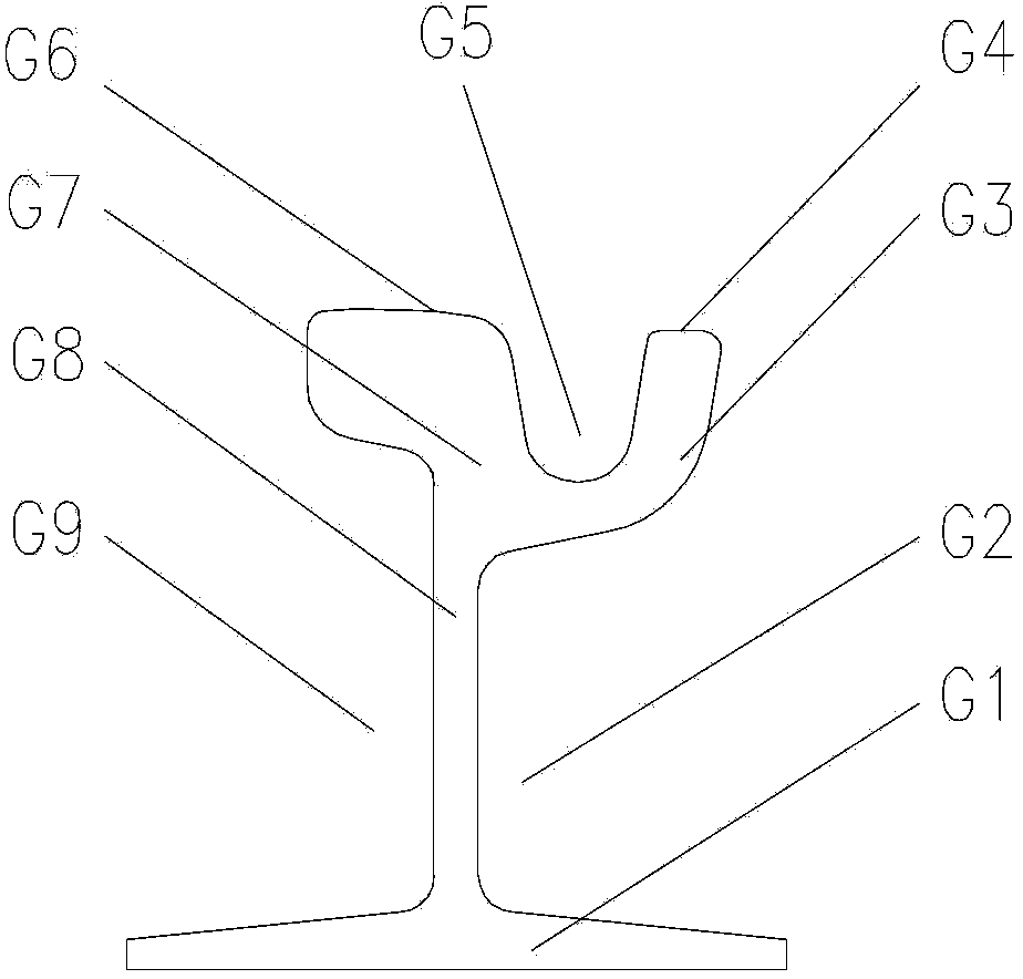
2) The pusher knife for removing weld burrs needs to have a protrusion that extends downward into the grooved steel rail, so it is easy to interfere and get stuck and cannot be opened
3) Since the perimeter of the section of the grooved steel rail is significantly longer than that of the traditional symmetrical section of the I-shaped rail, the resistance to removing weld bumps is significantly increased, and the pressure of the original oil cylinder needs to be increased when the space size is limited.

Method used


Image

  • Channel steel rail flash welding machine
  • Channel steel rail flash welding machine
  • Channel steel rail flash welding machine

Examples


Embodiment 1

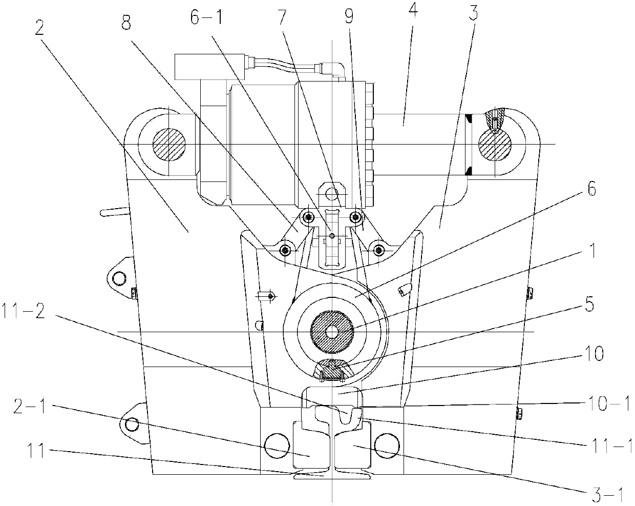
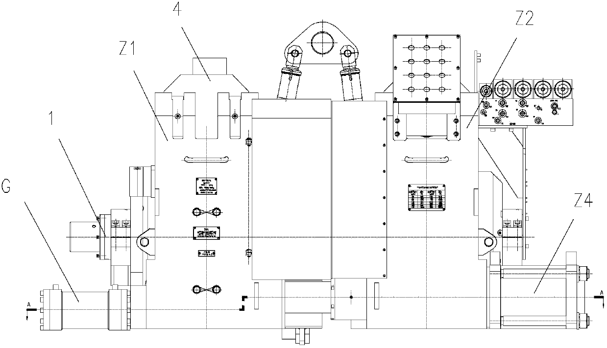
[0029] The basic structure of the channel rail flash welding machine of the present embodiment is as follows: figure 2 , 3 , 4, the lower part of the front box body part Z1 and the rear box body part Z2 constitutes a horizontal movement pair through the cylinder axis Z3. Front box body part Z1 and rear box body part Z2 are made of left and right clamp box body 2,3 and 2 ', 3 ' hinged on the central hinge shaft 1 respectively. The inner end of the front box body part Z1 is equipped with a tumor-removing knife T, and the outer end is equipped with a tumor-removing oil cylinder G that drives the tumor-removing knife T. The outer side of the rear box body part Z2 is equipped with an upsetting oil cylinder Z4 that drives the relative movement of the front box body part Z1 and the rear box body part Z2. The welding transformer Z5 is placed in the left and right clamp boxes, and the lower parts of the left and right clamp boxes 2, 3 and 2', 3' respectively have left and right jaws...


PUM


Abstract

The invention relates to a channel steel rail flash welding machine, which belongs to the technical field of traffic facility construction. A front box body component and a back box body component of the machine are constructed by left and right clamp box bodies hinged onto a center shaft respectively; a tumor push knife is arranged at the inner end of the front box body component; a tumor push oil cylinder for driving the tumor push knife is arranged at the outer end of the front box body component; an upsetting oil cylinder for driving the front box body component and the back box body component to move oppositely are arranged on the outer side of the back box body component; the upper ends of the left and right clamp box bodies are hinged together with the two ends of a clamping oil cylinder which extends and contracts horizontally respectively; a hoisting shaft sleeve from the lower part of which positioning surfaces extend is sleeved on a central hinged shaft; the positioning surfaces are provided with parts contacted with the rail head treads and the rail lip treads of channel steel rails respectively; and the projection shapes of left and right jaws are at least partially matched with the shape of the rail waist slots of the channel steel rails respectively. According to the flash welding machine, welding of asymmetrical left and right channel steel rails can be completed without turning round and reversing, so that the labor intensity is lowered greatly, and the operation efficiency is increased remarkably.

Description

technical field [0001] The invention relates to a rail welding device, in particular to a grooved rail flash welding machine, which belongs to the technical field of traffic facility construction. Background technique [0002] The existing mobile flash welding machine is suitable for the welding of traditional I-shaped rails. Its typical structure is as described in the Chinese patent documents with application numbers 98105796.9 and 98106266.0 and 201110431236.7, including welding transformers, current carrying components and Electric contact device, one end of the fuselage is equipped with the top oil cylinder, and the other end is equipped with the clamping device; the clamping device includes the left and right clamp boxes whose middle parts are hinged to each other through a fixed central hinge shaft, and the left and right clamp boxes. The lower part has relatively raised left and right jaws respectively, and the upper ends of the left and right clamp boxes are respect...

Claims


Application Information

Patent Timeline
IPC IPC(8): E01B31/18
Inventor 黄腾飞夏青顺王有虹刘晓磊郦雪云黄思姬
Owner CHANGZHOU RUITAI ENG MASCH CO LTD
Learn More