Reinforced transmission shaft

A drive shaft and reinforced technology, which is applied in the field of automobile transmission, can solve the problems of inconvenient loading, high cost and general dynamic balancing effect, and achieve the effects of convenient loading, low cost and improved dynamic balancing effect.

Inactive Publication Date: 2013-11-06
JIANGSU JOYLONG AUTOMOBILE
View PDF0 Cites 1 Cited by
  • Summary
  • Abstract
  • Description
  • Claims
  • Application Information

AI Technical Summary

Problems solved by technology

Since the flange and the third welding fork are fixed by the flange and four bolts, nuts, and gaskets, the dynamic balance of each section is performed separately, the dynamic balance effect is general, and the cost is high, and it is not convenient to load

Method used


Image

  • Reinforced transmission shaft

Examples


Embodiment Construction

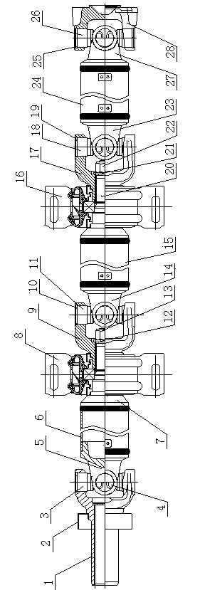
[0008] Such as figure 1 As shown, it is a reinforced transmission shaft, including a sliding fork 1, on which a torsional shock absorber 2 is arranged, and one end of the sliding fork 1 is connected to the first welding fork 5 through the first cross shaft assembly 3 and the first snap ring 4 , the other end of the first welding fork 5 is connected to the first shaft tube 6, the other end of the first shaft tube 6 is connected to the first non-sliding shaft 7, the first intermediate support assembly 8 is arranged on the first non-sliding shaft 7, the first The other end of the non-sliding shaft 8 is placed outside the first non-sliding fork 9 and fixed by the first washer 12 and the first nut 13, and the first non-sliding fork 9 is connected to the first non-sliding fork 9 through the second cross shaft assembly 11 and the second snap ring 10. Two welding forks 14, the other end of the second welding fork 14 is connected to the second shaft tube 15, the other end of the second...


PUM


Abstract

A reinforced transmission shaft relates to the technical field of car transmission, and comprises a slip yoke; one end of the slip yoke is connected with a first weld yoke; the other end of the first weld yoke is connected with a first shaft pipe; the other end of the first shaft pipe is connected with a first non-slip shaft; a first non-slip yoke sheaths the other end of the first non-slip shaft, and connected with a second weld yoke; the other end of the second weld yoke is connected with a second shaft pipe; the other end of the second shaft pipe is connected with a second non-slip shaft; a third weld yoke is arranged at the other end of the second non-slip shaft; the other end of the third weld yoke is connected with a third shaft pipe; the other end of the third shaft pipe is connected with a fourth weld yoke; the fourth weld yoke is connected with a flange yoke; a second non-slip yoke sheaths the other end of the second non-slip shaft, and the other end of the second non-slip shaft is fixed by a second gasket and a second nut; the second non-slip yoke is connected with the third weld yoke through a third cross assembly and a third snap ring. The reinforced transmission shaft adopts an integrated transmission shaft, is low in cost and convenient to load, and improves the dynamic balance effect greatly.

Description

technical field [0001] The invention relates to the technical field of automobile transmission. Background technique [0002] The existing drive shaft includes a sliding fork, on which a torsional shock absorber is arranged, one end of the sliding fork is connected to the first welding fork through the first cross shaft assembly and the first snap ring, and the other end of the first welding fork is connected to the first welding fork. Shaft tube, the other end of the first shaft tube is connected to the first non-sliding shaft, the first intermediate support assembly is arranged on the first non-sliding shaft, the other end of the first non-sliding shaft is placed outside the first non-sliding fork and passes through the first The washer and the first nut are fixed, the first non-sliding fork is connected to the second welding fork through the second cross shaft assembly and the second snap ring, the other end of the second welding fork is connected to the second shaft tube...

Claims


Application Information

Patent Timeline
Patent Type & Authority Applications(China)
IPC IPC(8): F16D3/26
Inventor 程志帅
Owner JIANGSU JOYLONG AUTOMOBILE
Why Eureka
Try Eureka