
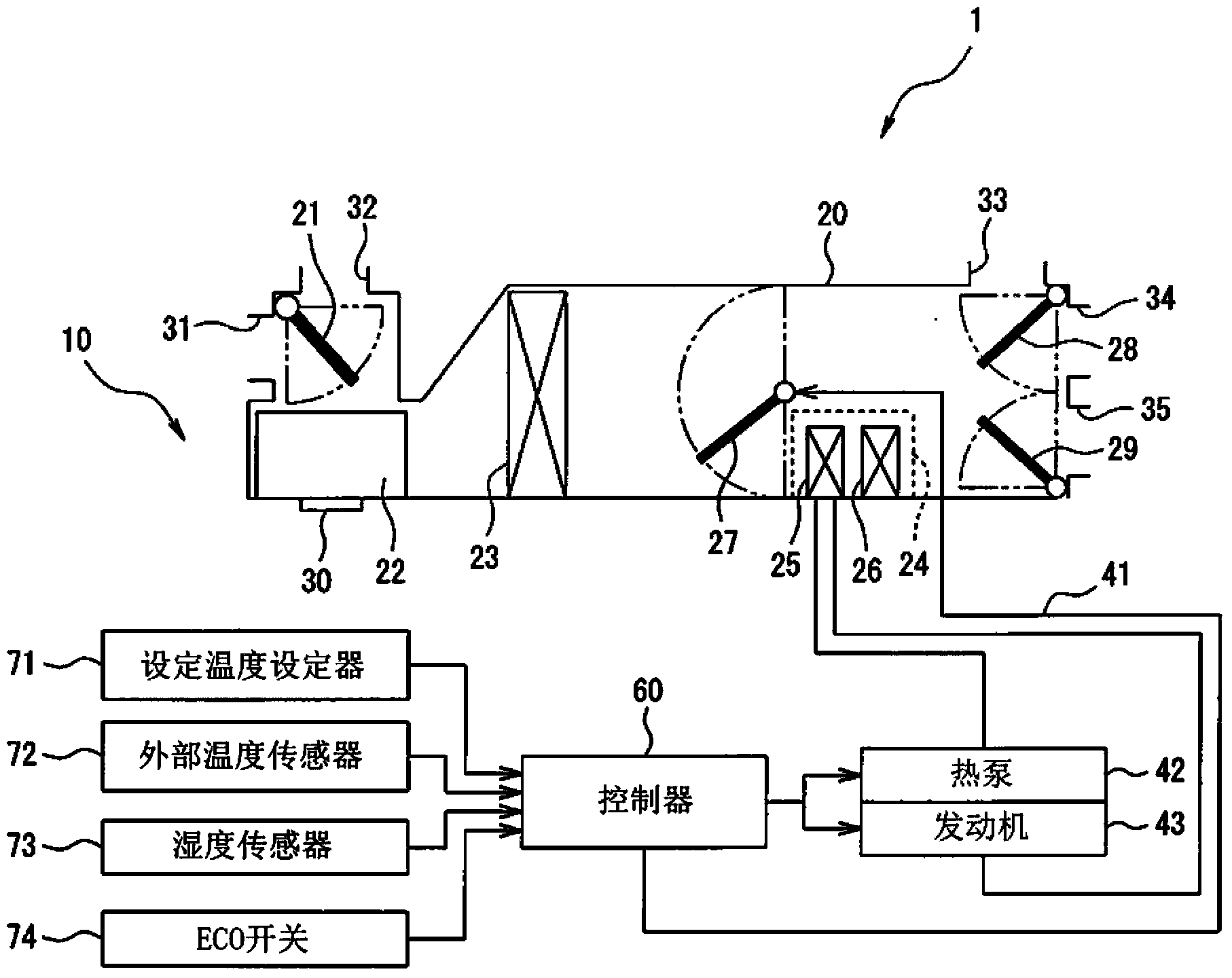
Air conditioning system for vehicles

An air conditioning system, air technology, applied in air handling equipment, vehicle components, heating/cooling equipment, etc., can solve the problems of reducing mileage, increasing electric heater power consumption, increasing air conditioning heating energy, etc.

Inactive Publication Date: 2013-11-06
SUZUKI MOTOR CORP
View PDF6 Cites 9 Cited by
  • Summary
  • Abstract
  • Description
  • Claims
  • Application Information

AI Technical Summary

Problems solved by technology

Therefore, in order to increase the heating energy of the air conditioner, it is necessary to increase the power consumption of the electric heater, which leads to a reduction in the mileage per unit of power.

Method used


Image

  • Air conditioning system for vehicles
  • Air conditioning system for vehicles
  • Air conditioning system for vehicles

Examples


no. 2 approach

[0138] Next, an air conditioning system according to a second embodiment of the present invention is described. In the second embodiment, the same parts as those of the first embodiment denoted by the same reference numerals will be omitted or simplified to avoid redundant description.

[0139] The structure and / or function of the air conditioning system according to the second embodiment are mostly the same as those of the air conditioning system according to the first embodiment except for the following points. Therefore, these differences will be mainly described below.

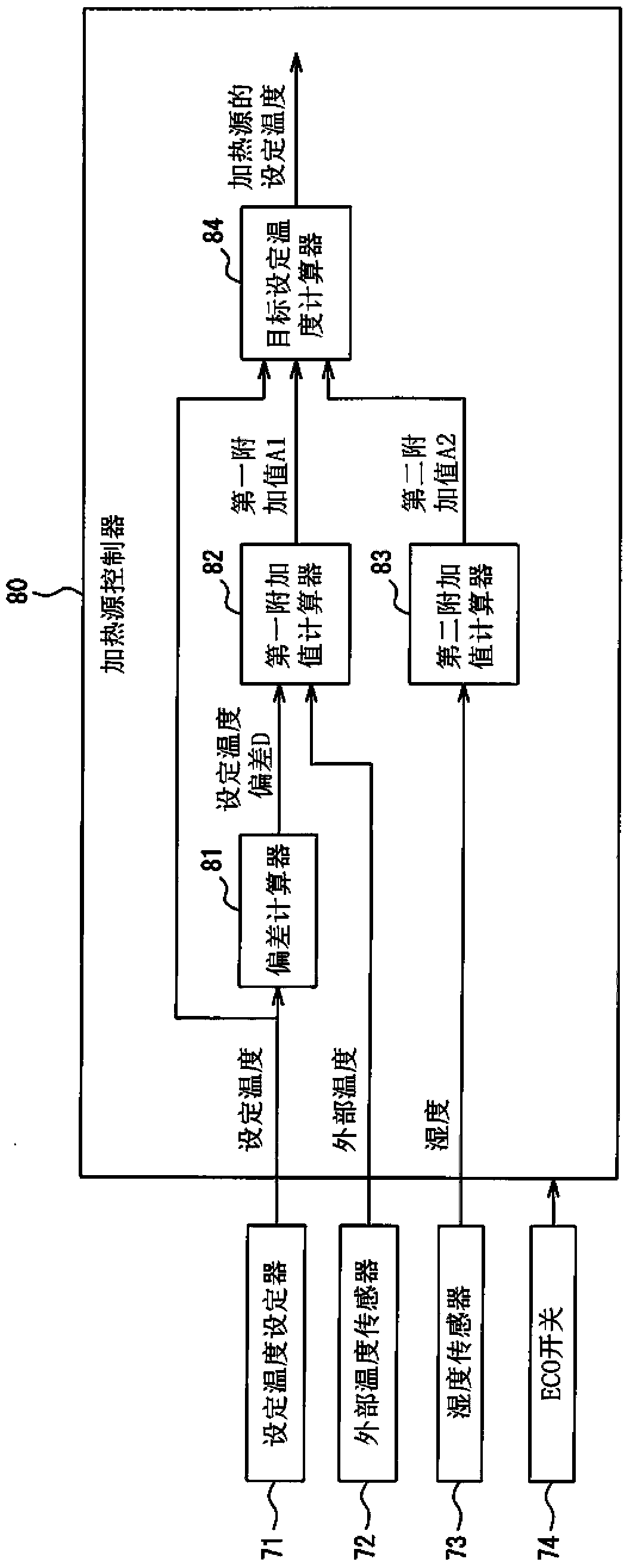
[0140] The air conditioning system according to the second embodiment is designed to change the first added value and the second added value according to the on or off state of the ECO switch 74 .

[0141] Figure 8 schematically shows the method used to calculate the target set temperature of the heating source 44 according to the present embodiment Figure 4 Subroutine in step S1.

[0142] refer to ...


PUM


Abstract

In an air conditioning system, a control unit controls an adjusting unit to adjust a ratio between an amount of a first part of introduced air passing through a heater core and an amount of a second part of the introduced air bypassing the heater core to a first ratio at which the amount of the first part of the introduced air decreases from a maximized amount of the first part of the introduced air according to an increase in temperature of the heater core by a warming unit. When a setting temperature for air conditioning is increased by an input unit, the control unit controls the adjusting unit to change the ratio from the first ratio to a second ratio at which the amount of the first part of the introduced air increases.

Description

technical field [0001] The present invention relates to techniques for controlling air conditioning in a vehicle. Background technique [0002] The air conditioning system is installed in the vehicle cabin for controlling the air conditioning in the vehicle cabin to maintain passenger comfort in the vehicle cabin. [0003] Every air conditioning system is generally designed to move the air mix damper, ie, the air mix door, into the appropriate position to regulate the amount of air passing through the heater core, thereby controlling The temperature of the air blown from the corresponding air conditioning system, thereby controlling the air conditioning in the vehicle compartment. [0004] For such an air conditioning system, it is necessary to provide passenger comfort in the passenger compartment as quickly as possible and to reduce the operation of the air conditioning system by the passengers. If air conditioning systems meet these requirements, their marketability can...

Claims


Application Information

Patent Timeline
IPC IPC(8): B60H1/00
CPCB60H1/00785B60H1/00007B60H1/00885B60H1/00835B60H1/0073B60H2001/00733
Inventor 桥谷英树百濑坚祐
Owner SUZUKI MOTOR CORP
Learn More