Motor rotor and motor with same

A technology of motor rotor and rotor iron core, applied in the direction of magnetic circuit rotating parts, DC commutator, electrical components, etc. problems such as failure to achieve the effect of improving production efficiency

Inactive Publication Date: 2013-10-30
JOHNSON ELECTRIC SHENZHEN
View PDF7 Cites 2 Cited by
  • Summary
  • Abstract
  • Description
  • Claims
  • Application Information

AI Technical Summary

Problems solved by technology

However, during the assembly process, due to the use of adhesives, it is necessary to go through the process of adding adhesives and waiting for the adhesives to dry, resulting in low production efficiency
Moreover, when a motor with such a rotor is used in a special environment, such as an environment full of gas, the adhesive is easy to volatilize and stick to the surface of the commutator, which will cause the motor to fail

Method used


Image

  • Motor rotor and motor with same
  • Motor rotor and motor with same
  • Motor rotor and motor with same

Examples


Embodiment Construction

[0015] The technical solutions and other beneficial effects of the present invention will be made obvious by describing the specific embodiments of the present invention in detail below in conjunction with the accompanying drawings.

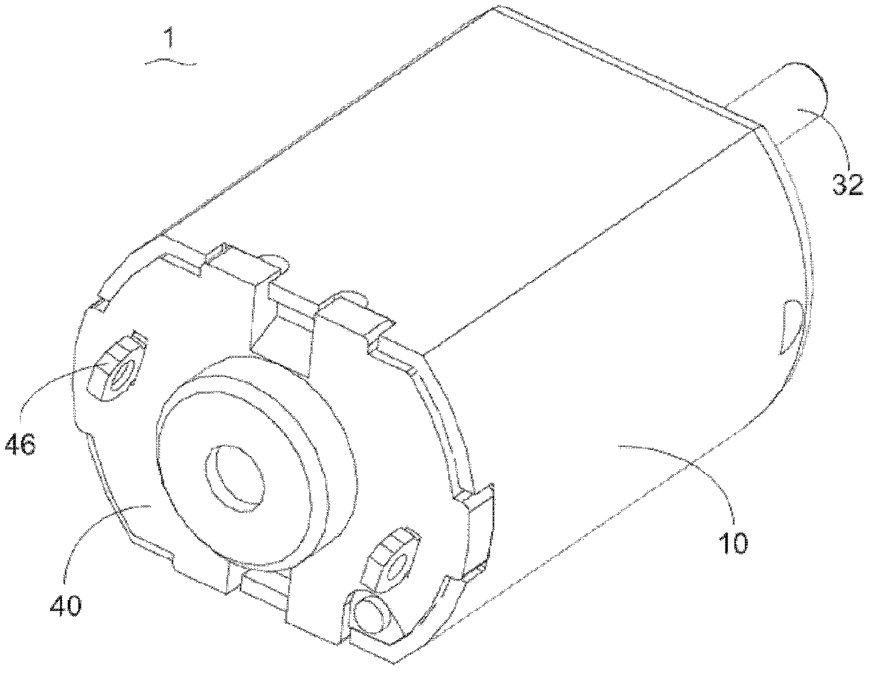
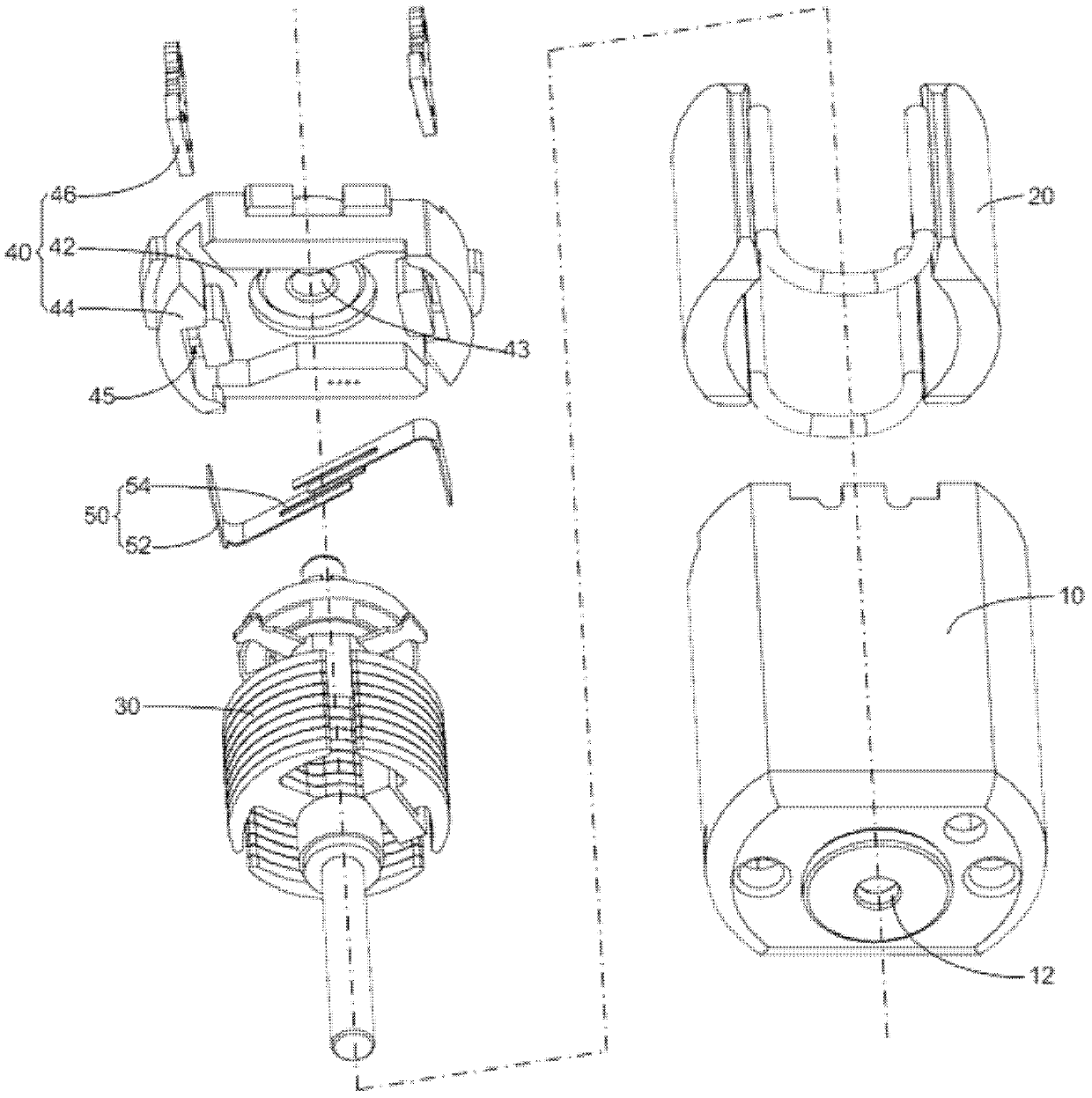
[0016] See figure 1 and figure 2 The motor 1 of the preferred embodiment of the present invention includes a housing 10, a plurality of permanent magnets 20, a rotor 30, an end cover 40 and a plurality of brushes 50.

[0017] The housing 10 is roughly cup-shaped, and a first through hole 12 for accommodating a bearing is opened at the bottom. The permanent magnet 20 is approximately in the shape of a curved sheet and is fixed to the inner wall of the housing 10 to form a space for accommodating the rotor 30.

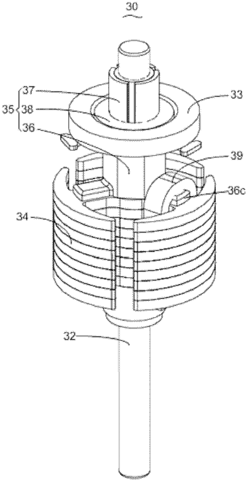
[0018] Please combine Figure 3 to Figure 5 The rotor 30 includes a rotating shaft 32, a rotor core 34, a commutator 35 and a plurality of coils 39 (only one coil is shown in the figure).

[0019] The rotor core 34 includes a cylindrical tooth ro...


PUM


Abstract

A commutator motor has a stator, brushes and a rotor. The rotor has a shaft, a rotor core fixed to the shaft, a number of coils wound about the rotor core and a commutator fixed to the shaft next to the rotor core. The commutator has a base and a number of commutator bars fixed to the base in sliding contact with the brushes. The rotor core includes a number of pole bodies extending substantially radially outwards. Each pole body includes a connecting surface at an axial end of the rotor core. The commutator base includes a number of connecting arms extending substantially radially outwards and contacting the connecting surfaces of corresponding pole bodies. At least two of the coils are wound around a corresponding pole body and the connecting arm contacting the connecting surface of this pole body.

Description

Technical field [0001] The present invention relates to a motor, in particular to a fixing method of a commutator and a rotor core in the rotor of the motor. Background technique [0002] An existing motor rotor includes a rotor core, a commutating bracket, and a commutating piece. The commutating piece is fixed to the commutating bracket to form a commutator. The commutating bracket is fixed to the rotor iron through an adhesive, such as glue. core. However, in the assembly process, since the adhesive is used, the process of adding the adhesive and waiting for the adhesive to dry is required, resulting in low production efficiency. Moreover, when a motor with such a rotor is used in a special environment, such as a gas-filled environment, the adhesive is easy to volatilize and adhere to the surface of the commutator segment, which will cause the motor to fail. Summary of the invention [0003] In view of this, it is necessary to provide a motor rotor that has high production ef...

Claims


Application Information

Patent Timeline
Patent Type & Authority Applications(China)
IPC IPC(8): H02K1/27H02K23/00
CPCH02K13/04H02K13/006H02K13/105
Inventor 刘清式潘广业黄宁何婷金建平
Owner JOHNSON ELECTRIC SHENZHEN
Why Eureka
Try Eureka