Method and system for continuously manufacturing optical display panel
A technology of optical display panels and manufacturing methods, applied in chemical instruments and methods, optics, nonlinear optics, etc., can solve problems such as poor image display, and achieve the effect of eliminating deflection
- Summary
- Abstract
- Description
- Claims
- Application Information
AI Technical Summary
Problems solved by technology
Method used
Image

Examples
Embodiment approach 1
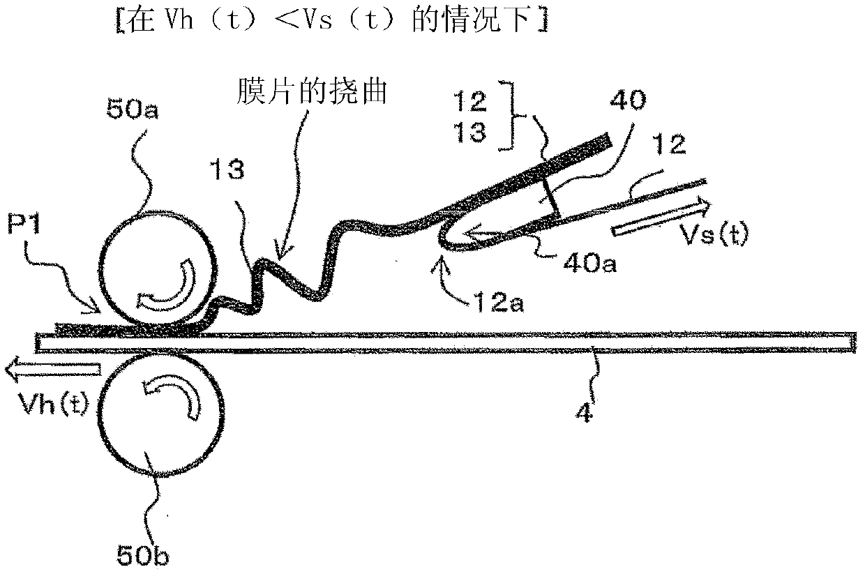
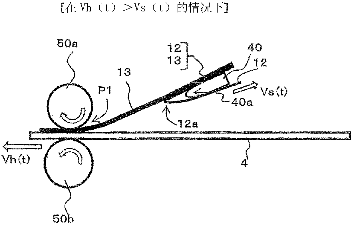
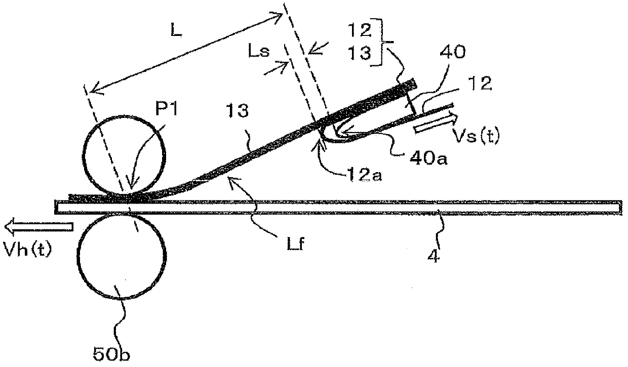
[0065] The continuous manufacturing system of the optical display panel according to the present embodiment includes a carrier film conveying unit for conveying the carrier film of the film sheet to which the polarizing film is attached via an adhesive, and a peeling unit for utilizing the The top end is used to fold back the carrier film conveyed by the above-mentioned carrier film conveying part to the inside, so as to peel off the film sheet together with the adhesive from the carrier film; A carrier film winding; a sticking part for forming an optical display panel by sticking the film sheet peeled from the carrier film by the above-mentioned peeling part on the optical unit with an adhesive while conveying the optical unit; and a speed control part It is used to control the conveyance speed of the said winding part and the said sticking part.
[0066]Further, the speed control unit performs setting and control such that the sticking speed of the sticking process by the st...
Embodiment approach 2
[0102] In Embodiment 2, a configuration different from that of Embodiment 1 described above will be described. The 1st carrier film conveying part 101 of Embodiment 2 has the downstream side film supply part 95 instead of the upstream side film supply part 90.
[0103] The downstream-side film supply part 95 is constituted by a feed roller, and is arranged at a position on the conveyance downstream side from the first peeling part 40 and on the conveyance upstream side from the first take-up part 60 (refer to Figure 4B ), the feed roller includes: a first roller 95a driven by an unillustrated motor; and a second roller 95b arranged opposite to the first roller 95a and driven by an unillustrated biasing member (for example, A compression spring, a leaf spring, etc.) are pressed toward the 1st roller 95a. The second roller 95b is driven by rotating the first carrier film 12 (the first carrier film 12 after peeling the film sheet 13) between the first roller 95a and the second ...
Embodiment approach 3
[0107] The third embodiment is configured to include both the upstream-side film supply part 90 of the above-described first embodiment and the downstream-side film supply part 95 of the second embodiment. The conveyance speed (Vs(t)) of the carrier film is controlled by both the upstream side film supply part 90 and the downstream side film supply part 95 . By arranging the film supply part (feed roller) on both upstream and downstream (upstream and downstream bounded by the first peeling part 40 ), the carrier film can be conveyed while applying tension to the carrier film. For example, tension can be applied to the carrier film between the upstream side and the downstream side by making the downstream supply speed (conveyance speed) faster than the upstream supply speed (conveyance speed).
PUM
 Abstract
Description
Claims
Application Information
 - R&D
- Intellectual Property
- Life Sciences
- Materials
- Tech Scout
- Unparalleled Data Quality
- Higher Quality Content
- 60% Fewer Hallucinations
Browse by: Latest US Patents, China's latest patents, Technical Efficacy Thesaurus, Application Domain, Technology Topic, Popular Technical Reports.
© 2025 PatSnap. All rights reserved.Legal|Privacy policy|Modern Slavery Act Transparency Statement|Sitemap|About US| Contact US: help@patsnap.com