Printing unit with jet or spray device for cleaning fluid

A technology of printing device and spraying device, applied in printing, printing press, rotary printing press, etc., can solve problems and make effective contributions.

Active Publication Date: 2017-03-01
海德堡印刷机械知识产权股份两合公司
View PDF3 Cites 0 Cited by
  • Summary
  • Abstract
  • Description
  • Claims
  • Application Information

AI Technical Summary

Problems solved by technology

[0003] Neither DE 10 2005 024 285 B5, in which a spraying device with a droplet guard is described, nor DE 10 2011 103 804 A1, in which a spray bar with an actuating rod and a collecting trough is described, can make an effective contribution to solving the mentioned problems

Method used


Image

  • Printing unit with jet or spray device for cleaning fluid
  • Printing unit with jet or spray device for cleaning fluid

Examples


Embodiment Construction

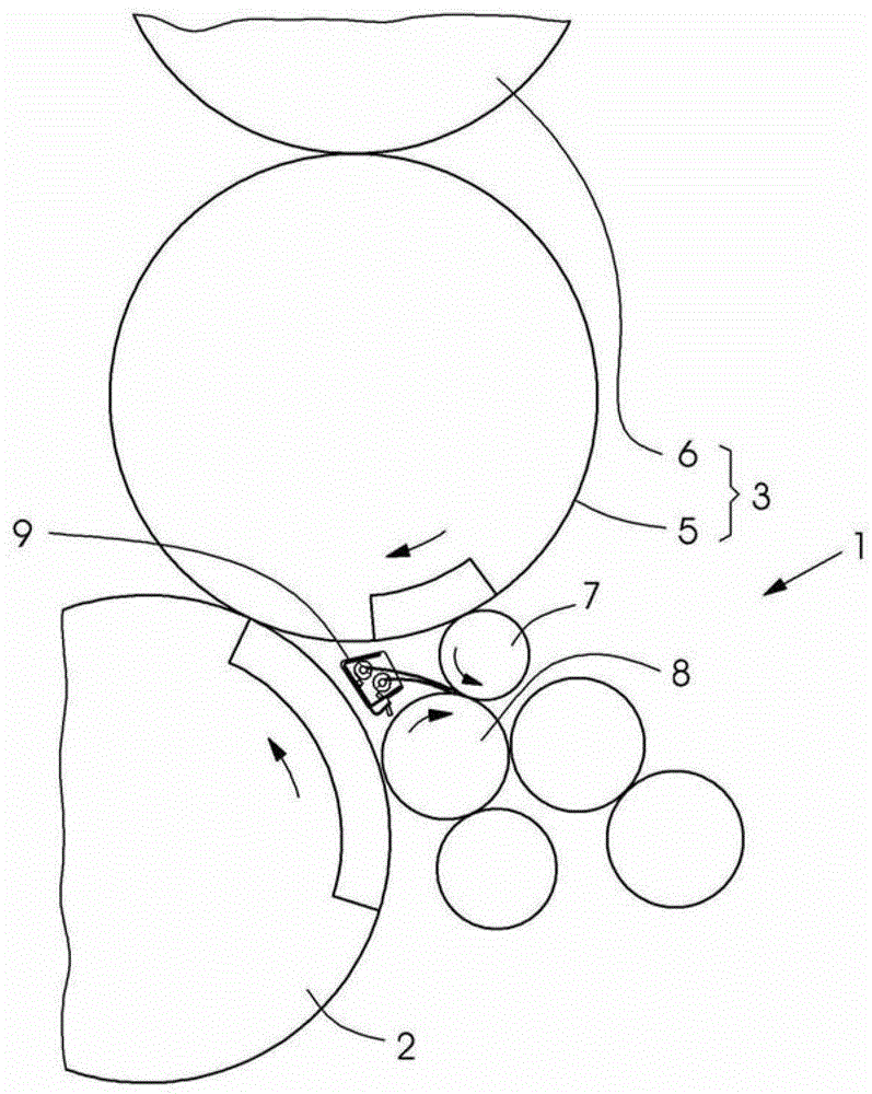
[0024] figure 1 A printing press for offset or planar printing on sheet-fed printing materials is shown in fragments. A printing unit 1 with a printing form cylinder 2 is shown in this partial view. The blanket cylinder and counter-pressure cylinder of the printing unit 1 are not shown. In addition, an anilox inking unit 3 and a dampening unit 4 belong to the printing unit 1 . The anilox roller inking unit 3 comprises an inking roller 5 and an anilox roller 6 . During printing operation, the inking roller 5 rests against the anilox roller 6 and the plate cylinder 2 . The dampening device 4 is not a spray-wetting unit, but a film dampening unit with dip rollers (no reference numerals) for drawing up dampening agent from a dampening box (not shown). Furthermore, the dampening unit 4 comprises a first dampening unit roll 7 and a second dampening unit roll 8 . The first dampening unit roller 7 is a connecting roller for connecting the dampening unit 4 to the anilox roller ink...


PUM


Abstract

The printing element (1) has a radiation or spraying device (9) that is provided for a cleaning liquid. The radiation or spraying device is provided with housing (10). A base (13) is relatively inclined to the horizontal outer surface (14). The radiation or spraying device is directed away from the ink application roller (5). The radiation or spraying device is directed to one of the dampening rollers (7,8).

Description

technical field [0001] The invention relates to a printing unit comprising a jetting or spraying device for cleaning fluid. Background technique [0002] No. 7,373,882 B2 describes a printing unit with a spraying or spraying device having a detergent nozzle and a water nozzle. As a result, detergent and water are sprayed into an inlet wedge, which a dampening roller forms together with a dampening roller. The installation location of the spraying device is not dangerous with respect to dripping of cleaning fluid residues. However, for certain use cases it may be desirable to install the sprinkler device in hazardous installation locations. One reason for this may be that there is not enough installation space available for installing the spraying device in a non-hazardous installation location. A further reason could be that the dangerous installation position makes more effective cleaning possible. [0003] Neither DE 10 2005 024 285 B5, which describes a spraying devic...

Claims


Application Information

Patent Timeline
Patent Type & Authority Patents(China)
IPC IPC(8): B41F7/20B41F35/06
CPCB41F35/002B41P2235/26
Inventor D·沙夫拉特
Owner 海德堡印刷机械知识产权股份两合公司
Why Eureka
Try Eureka