Plunger ball position checking tool

A ball position and inspection tool technology, applied in measuring devices, instruments, mechanical devices, etc., can solve the problems of batch detection of plunger ball position detection efficiency, low detection accuracy, detection error of ball position inspection tools, etc., and achieve detection efficiency. And the effect of high detection accuracy and easy batch detection

Active Publication Date: 2013-10-23
WUXI YINGBEI PRECISION BEARING
View PDF6 Cites 3 Cited by
  • Summary
  • Abstract
  • Description
  • Claims
  • Application Information

AI Technical Summary

Problems solved by technology

[0002] The traditional plunger ball position inspection tool does not use the ball head to locate the ball head, but the outer diameter end surface to detect the ball head. In practice, the ball head and the outer diameter have a jump (that is, the center line is inconsistent), which makes the ball position inspection tool have a certain role in the detection. Error, the detection efficiency and detection accuracy are relatively low when detecting the plunger ball position in batches

Method used


Image

  • Plunger ball position checking tool
  • Plunger ball position checking tool

Examples


Embodiment Construction

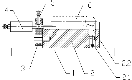
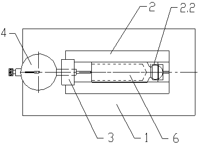
[0017] see figure 1 and figure 2 , The present invention relates to a plunger ball position inspection tool, which includes a base 1, a detection positioning seat 2 is fixedly arranged on the upper surface of the base 1, and the top right half of the detection positioning seat 2 is provided with a downward Ball head positioning hole, the ball head positioning hole is provided with a telescopic spring 2.1 and a ball head positioning block 2.2 from bottom to top, the telescopic spring 2.1 is arranged vertically, and the upper end of the telescopic spring 2.1 and the ball head positioning block 2.2 The bottom of the ball head positioning hole can be a blind hole, then the lower end of the telescopic spring 2.1 is connected to the bottom of the blind hole, the ball head positioning hole can be a through hole, then the lower end of the telescopic spring 2.1 and the base below the through hole 1 connection, the upper surface of the ball head positioning block 2.2 is provided with ...


PUM


Abstract

The invention relates to a plunger ball position checking tool. The plunger ball position checking tool is characterized by comprising a base (1), wherein the base (1) is provided with a detection positioning seat (2), a downward ball head positioning hole is formed in the top of the detection positioning seat (2), a stretchable spring (2.1) and a ball head positioning block (2.2) are arranged inside the ball head positioning hole from bottom to top, the upper end of the stretchable spring (2.1) is connected with the bottom of the ball head positioning block (2.2), a longitudinal first limiting groove is formed in the upper surface of the ball head positioning block (2.2), a transverse second limiting groove is formed in the top of the detection positioning seat (2) at the left side of the ball head positioning hole, the left end of the detection positioning seat (2) is connected with a dial gauge frame (3), and a rightward dial gauge (4) is fixed to the dial gauge frame (3). The plunger ball position checking tool has the advantages of bringing convenience to batch detection, and being high in detection efficiency and detection accuracy.

Description

technical field [0001] The invention relates to a plunger ball position inspection tool, which belongs to the technical field of tool inspection tools. Background technique [0002] The traditional plunger ball position inspection tool is not positioned with the ball head, but the outer diameter end face is positioned to detect the ball head. In fact, the ball head and the outer diameter have a jump (that is, the center line is inconsistent), which makes the ball position inspection tool in the detection. Error, the detection efficiency and detection accuracy are relatively low when testing the plunger ball position in batches. Therefore, it is particularly important to seek a plunger ball position inspection tool that is convenient for batch inspection, and has high inspection efficiency and inspection accuracy. SUMMARY OF THE INVENTION [0003] The purpose of the present invention is to overcome the above deficiencies, and to provide a plunger ball position inspection t...

Claims


Application Information

Patent Timeline
IPC IPC(8): G01B5/00
Inventor 段勋严伟陈文昝茂荣蒋成国
Owner WUXI YINGBEI PRECISION BEARING
Why Eureka
Try Eureka