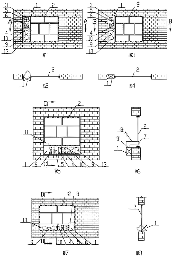
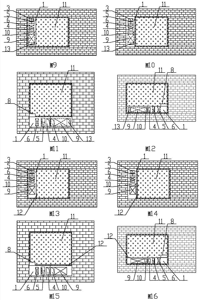
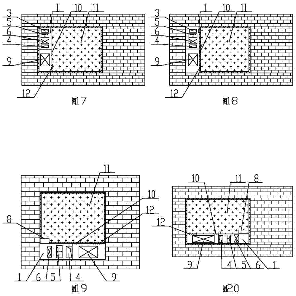
Fresh air unit with direct evaporative cooler and its passive cooling air conditioning unit
A technology for evaporative coolers and air-conditioning devices, which is applied to air-conditioning systems, heating methods, space heating and ventilation, etc. It can solve the problems of occupying building usable area, complex air supply duct systems, and difficult construction, and achieve increased new capacity. Air volume, flexible and convenient installation, and the effect of reducing construction difficulty
Active Publication Date: 2017-06-20
于向阳
View PDF1 Cites 0 Cited by
- Summary
- Abstract
- Description
- Claims
- Application Information
AI Technical Summary
Problems solved by technology
The present invention provides a fresh air unit with a direct evaporative cooler and its passive cooling air-conditioning device, which overcomes the deficiencies of the prior art, and can effectively solve the problem that the existing air-conditioning system adopts a centralized fresh air unit that requires an air-conditioning machine room to occupy the building Usable area, complex air supply duct system, need to install fire sprinkler facilities, difficult construction, and high operating costs
Method used
View moreImage
Smart ImageViewing Examples
Examples
Embodiment 1
Embodiment 2
Embodiment 3
Login to View More PUM
 Abstract
The invention relates to the technical field of building energy conservation, and relates to a fresh air unit with a direct evaporative cooler and a passive cooling air-conditioning device thereof. The terminal device air inlet and the terminal device air supply port are provided on the top, the shell fresh air port and the shell air supply port are provided on the shell, and the fresh air unit is provided in the shell, and the fresh air set includes a blower fan and a direct evaporative cooler. The invention has a reasonable and compact structure and is easy to use. Its shell is installed inside or outside the window, and the outdoor air introduced by the fresh air port of the shell is processed by the direct evaporative cooler and sent into the room. The air duct reduces the difficulty of construction, saves the height of the building, and can reduce auxiliary facilities such as air supply ducts and fire sprinkler pipes. It has the characteristics of convenient adjustment, good airtight performance, easy coordination with buildings, and safety and efficiency.
Description
Fresh air unit with direct evaporative cooler and its passive cooling air conditioning unit technical field The invention relates to the technical field of building energy saving, and relates to a fresh air unit with a direct evaporative cooler and a passive cooling air-conditioning device thereof. Background technique With the development of society and economy, people's requirements for the modern architectural environment are not only the function of sheltering from rain and wind, but also an environment with suitable temperature and humidity, fresh air, soft light, quiet and comfortable environment. The general method of traditional air conditioning systems is to supply fresh air to the room through centralized fresh air units, and install terminal devices in the room to control the indoor temperature and humidity. This method solves the problem of indoor temperature and humidity, but the centralized supply of fresh air requires building There is an air-conditioning ma...
Claims
Login to View More Application Information
Patent Timeline
 Patent Type & Authority Patents(China)
IPC IPC(8): F24F5/00
Inventor 于向阳
Owner 于向阳
Features
- R&D
- Intellectual Property
- Life Sciences
- Materials
- Tech Scout
- Unparalleled Data Quality
- Higher Quality Content
- 60% Fewer Hallucinations
Learn More Browse by: Latest US Patents, China's latest patents, Technical Efficacy Thesaurus, Application Domain, Technology Topic, Popular Technical Reports.
© 2025 PatSnap. All rights reserved.Legal|Privacy policy|Modern Slavery Act Transparency Statement|Sitemap|About US| Contact US: help@patsnap.com


