
a stop device

A technology of stop device and stop block, which is applied in the direction of workpiece clamping device, metal processing, metal processing equipment, etc., to achieve the effect of improving reliability and simple operation

Active Publication Date: 2015-09-02
XIANGTAN ELECTRIC MFG CORP LTD
View PDF10 Cites 0 Cited by
  • Summary
  • Abstract
  • Description
  • Claims
  • Application Information

AI Technical Summary

Problems solved by technology

Factors such as deviations in processing dimensions, deformation of parts, changes in mechanical properties, and changes in operating conditions will cause hidden dangers of relative displacement between shaft parts and collar parts with transition and interference fit.

Method used


Image

  • a stop device
  • a stop device
  • a stop device

Examples


Embodiment Construction

[0013] The present invention will be further described below in conjunction with accompanying drawing and embodiment:

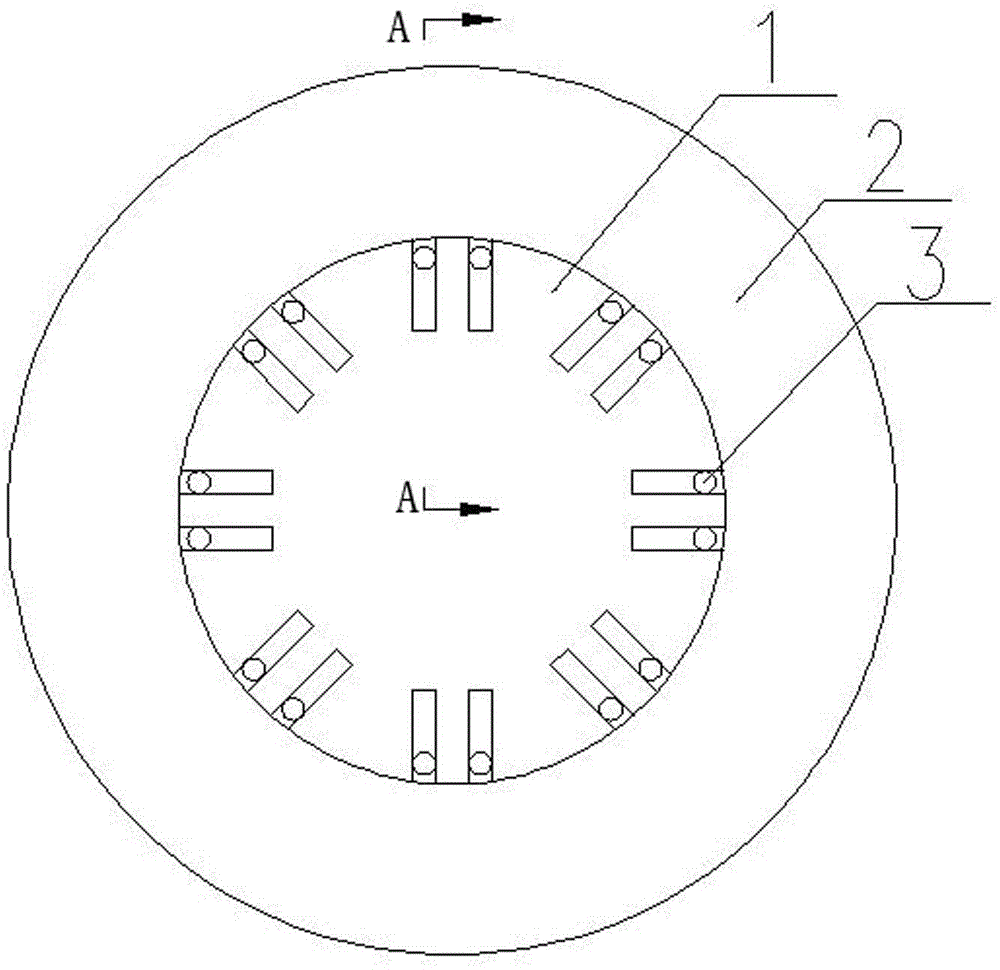
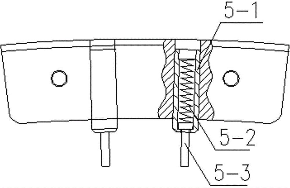
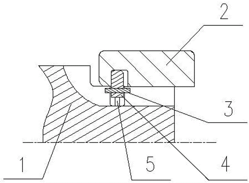
[0014] Referring to the accompanying drawings, a stop device includes a shaft body 1, a collar 2, a block 3, a stop block 4, and an elastic device 5. The inner circle of the collar 2 and the outer circle of the shaft body 1 are assembled on the Together, grooves are respectively provided at positions corresponding to the inner circle of the collar 2 and the outer circle of the shaft body 1. In order to facilitate processing and installation of a plurality of stoppers 4 and elastic devices 5, the grooves are annular grooves; To facilitate installation, one end of the elastic device 5 is connected to the bottom of the shaft body 1 or the annular groove of the collar 2, and the other end is connected to the stop block 4; the stop block 4 and the elastic device 5 are placed in the sleeve In the groove of the ring 2 and the shaft body 1, the sum of the heights of ...


PUM


Abstract

The invention relates to a stopping device. The stopping device comprises a shaft body and a lantern ring, wherein the inscribed circle of the lantern ring and the circumscribed circle of the shaft body are assembled together. The stopping device is characterized by further comprising stop blocks and elastic devices, grooves are respectively formed in the corresponding positions of both the inner circle of the lantern ring and the excircle of the shaft body, the stop blocks and the elastic devices are arranged in the grooves of the lantern ring and the shaft body, one end of each elastic device is connected with the lantern ring or the shaft body, the other ends of the elastic devices are connected with the stop blocks, and the total height of the completely compressed elastic devices and the stop blocks is less than or equal to the depth of the grooves, where the elastic devices are positioned, in the lantern ring or the shaft body. As the stop blocks are arranged between the lantern ring and the shaft body, the assembly body of both the lantern ring and the shaft body can be positioned in the axial direction. The assembly is simple and quick, and the assembly reliability between the shaft body and the lantern ring can be effectively improved.

Description

technical field [0001] The invention relates to a stop device. Background technique [0002] The assembly structure of shaft parts and collar parts is widely used in various mechanical and electrical products, and this structure is generally located in the key parts of various products, such as the transmission position, the outer circle of key parts Protect. This type of structure is mostly realized through transition and interference fit between the shaft body and the collar. During assembly, the assembly is usually achieved by thermal expansion, hydraulic expansion of the collar, or cold contraction of the shaft body. Factors such as deviations in processing dimensions, deformation of parts, changes in mechanical properties, and changes in operating conditions will cause hidden dangers of relative displacement between shaft parts and collar parts that are transitional and interference fit. Contents of the invention [0003] The object of the present invention is to o...

Claims


Application Information

Patent Timeline
Patent Type & Authority Patents(China)
IPC IPC(8): B23P11/00B25B11/00
Inventor 李楠晏明姚建荣易晓波郭晓玲
Owner XIANGTAN ELECTRIC MFG CORP LTD
Learn More