An improved film cutting machine

A technology of film cutting machine and film cutting knife, which is applied in the direction of sending objects, thin material processing, transportation and packaging, etc., which can solve the problems of low work efficiency, low degree of automation, and increased labor intensity of workers, so as to achieve automation and structure simple effect

Active Publication Date: 2016-02-24
ZHEJIANG HAIYUE AUTOMATIC MACHINERY
View PDF7 Cites 1 Cited by
  • Summary
  • Abstract
  • Description
  • Claims
  • Application Information

AI Technical Summary

Problems solved by technology

[0002] In the existing film cutting machine, the driving device rolls the film out of the film outlet, and then uses the film cutter at the film outlet to manually tear it off. The degree of automation is not high, the work efficiency is low, and the labor intensity of workers is increased.

Method used


Image

  • An improved film cutting machine
  • An improved film cutting machine
  • An improved film cutting machine

Examples


Embodiment approach 1

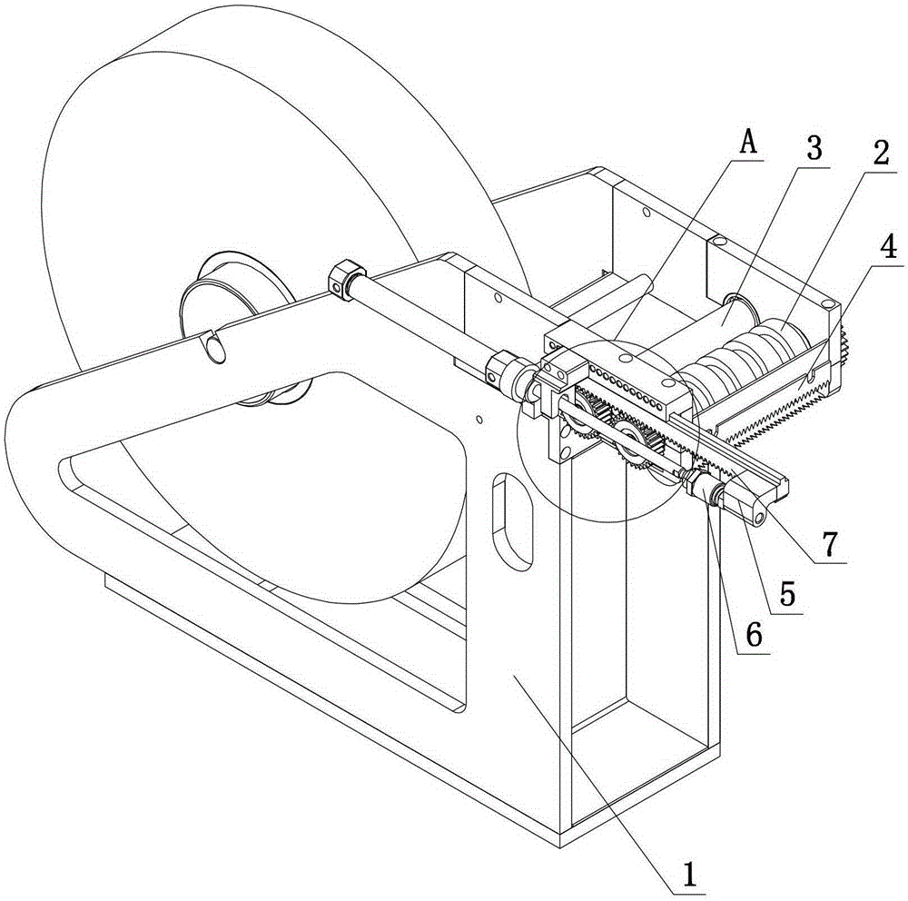
[0024] The driver adopts an air cylinder or a hydraulic cylinder, the end of the piston rod of the air cylinder or hydraulic cylinder is connected to the rack 7, and a connecting device is provided at the joint, and the connecting device is composed of a floating joint 6 and a rack connection block 5. During specific implementation, The floating joint 6 is connected to the end of the piston rod, the rack connection block 5 is fixed on the rack 7, and finally the floating joint 6 and the rack connection block 5 are fixed, so that the rack 7 is located on the side of the cylinder or the hydraulic cylinder. On one side, the rack 7 does not need to be fixed at the end of the piston rod, which saves space to a certain extent and makes the structure of the whole device more compact.

Embodiment approach 2

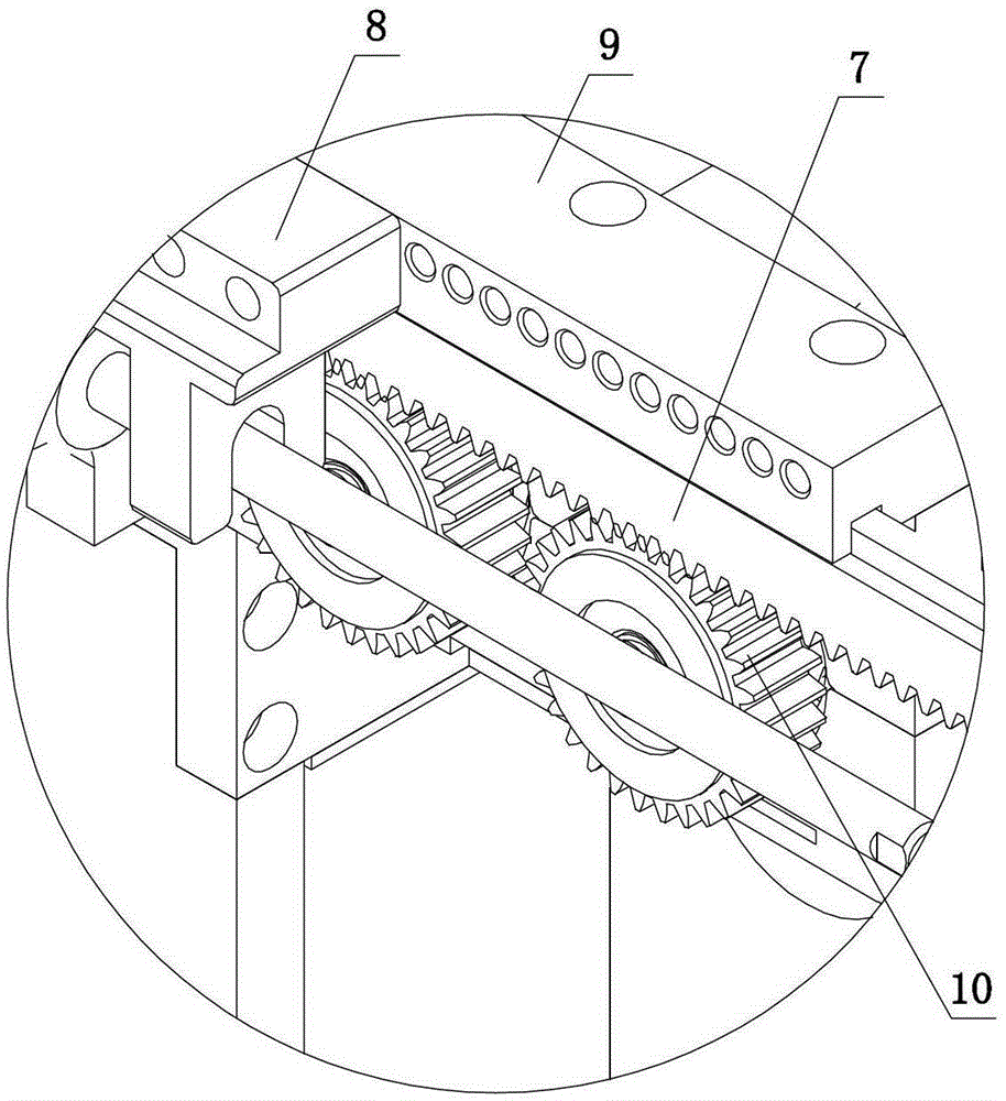
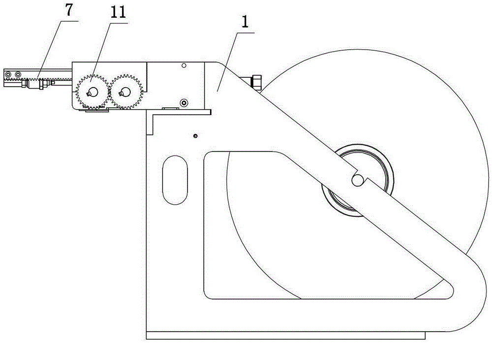
[0026] The driver adopts a motor, and the output end of the motor is provided with a driving gear, and the driving gear meshes with the rack 7. During specific implementation, the motor and the driving gear 10 are installed on the same side film roll support 1, and the output end After the driving gear is installed, the driving gear and the driving gear 10 are on the same horizontal plane, then the rack 7 is installed on the driving gear and the top of the driving gear 10, and the driving gear is driven by the motor to reciprocate. Therefore, the driving rack 7 is also reciprocating operation.

[0027] The specific embodiment of the above-mentioned driver, as a further improvement, a rack mounting seat 9 is provided above the rack 7, and one side of the rack mounting seat 9 is fixed on the film roll support 1, and at the bottom of the rack mounting seat 9 Set the limit groove, then set the raised portion matched with the limit groove on the top of the rack 7, install the raise...


PUM


Abstract

The invention discloses an improved film cutting machine which comprises a film rolling support and an automatic film cutting mechanism, wherein a film feeding roller component and a driving device are arranged on the film rolling support; the driving device drives the film feeding roller component to operate; a film outlet is formed on one side of the film feeding roller component; the automatic film cutting mechanism comprises a film cutting blade and a film cutting blade driver; the film cutting blade driver is fixed above the film rolling support at the film outlet; and the film cutting blade moves vertically through the film cutting blade driver. With the adoption of the technical scheme, the improved film cutting machine has the advantages as follows: the structure is simple, and the film cutting blade can cut off a film rolling out automatically, so that the automation of a film-cutting process is realized.

Description

technical field [0001] The invention relates to an improved film cutting machine. Background technique [0002] In the existing film cutting machine, the driving device rolls the film out of the film exit, and then uses the film cutting knife at the film exit to manually tear it off. The degree of automation is not high, the work efficiency is low, and the labor intensity of workers is increased. Contents of the invention [0003] The problem to be solved by the present invention is to provide an improved film cutting machine which has a simple structure and can automatically cut the film sent out from the roll. [0004] In order to solve the above technical problems, the present invention adopts the following technical solutions: an improved film cutting machine, including a film roll support, and a film feeding roller assembly and a driving device are arranged on the film roll support, and the driving device drives the film feeding roller assembly. The film roller assem...

Claims


Application Information

Patent Timeline
Patent Type & Authority Patents(China)
IPC IPC(8): B65H35/06
Inventor 林雁斌张建章倪燮逵周富成费明儿黄亮亮李瑞李征胡勇雄陈义忠张勇根
Owner ZHEJIANG HAIYUE AUTOMATIC MACHINERY
Why Eureka
Try Eureka