A high-quality wide-angle optical system

A wide-angle optical system and image quality technology, applied in the field of optical lenses, can solve the problems of difficult product acquisition, long lens, large volume, etc., and achieve the effects of good color reproduction, cost reduction, and overall uniformity.

Active Publication Date: 2015-08-19
UNION OPTECH
View PDF3 Cites 0 Cited by
  • Summary
  • Abstract
  • Description
  • Claims
  • Application Information

AI Technical Summary

Problems solved by technology

[0002] The currently used camera phone digital lenses generally have the following disadvantages: relatively low pixels, large dimensions
The current mainstream camera phones on the market are mainly low-configuration lenses of 2 million and 3 million pixels. The image quality of the captured images is not ideal in terms of overall clarity or uniformity of illumination, so they can only be used as standby screens or Ordinary appreciation, but far from enough to print exquisite photos; and the shape of the digital lens for camera phones is too large, the outer diameter is generally larger than M8, and the use of high-pixel chips is limited to the use of CCD photosensitive sheets, and CCD technology is controlled by Japanese manufacturers. , it is very difficult to obtain advanced products. At the same time, the lens used for CCD photosensitive film is relatively long, and the total length of the optical system is greater than 8mm. It is bulky when used on a built-in camera phone.

Method used


Image

  • A high-quality wide-angle optical system
  • A high-quality wide-angle optical system
  • A high-quality wide-angle optical system

Examples


Embodiment Construction

[0021] The present invention is described in detail below in conjunction with accompanying drawing:

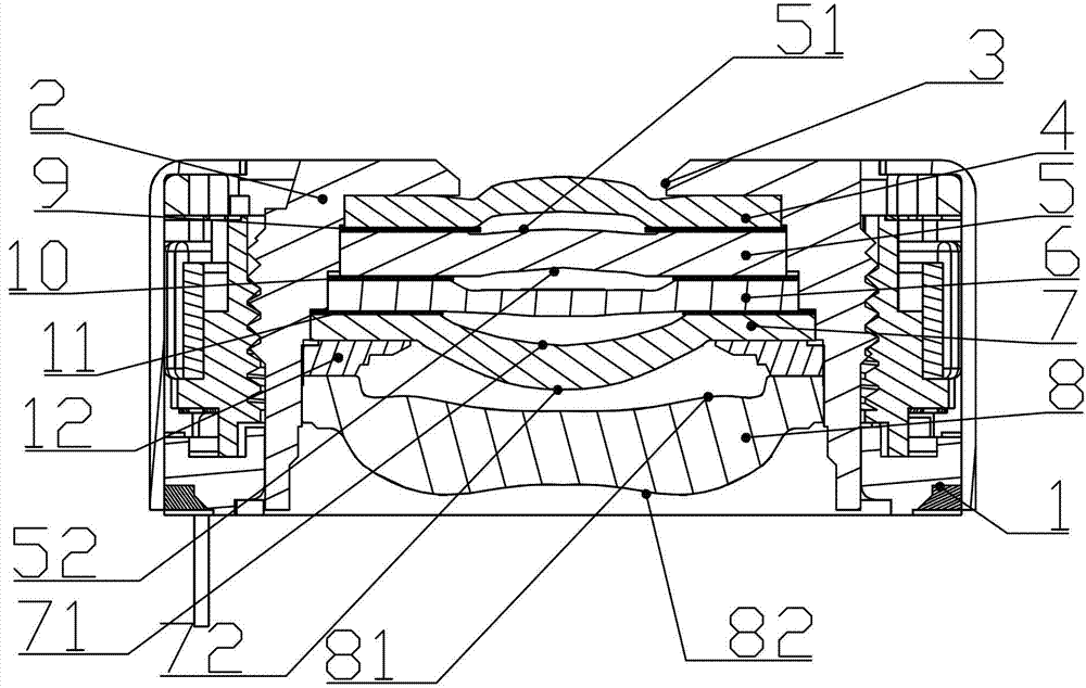
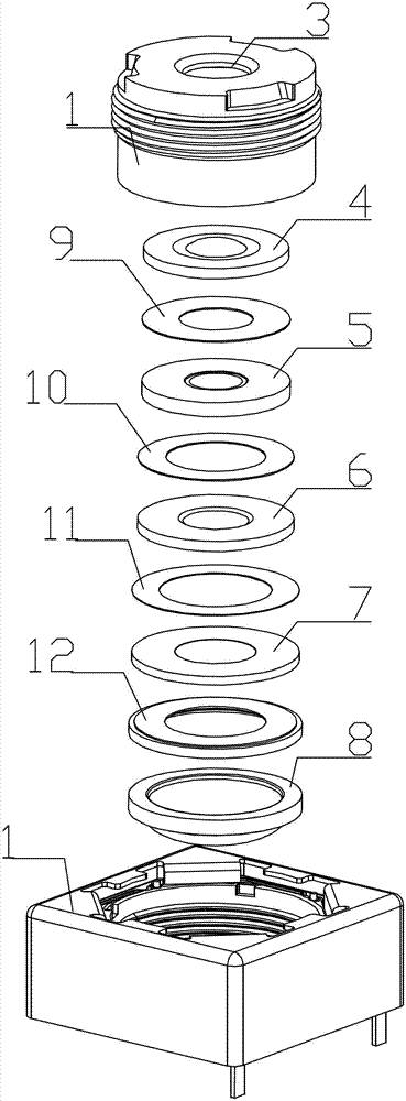
[0022] Such as figure 1 As shown, a high-quality wide-angle optical system can be used for relatively cheap high-pixel CMOS photosensitive sheets, including a seat 1 and a lens barrel 2 connected to the seat. In the cavity of the barrel 2, a first lens 4, a second lens 5, a third lens 6, a fourth lens 7, and a fifth lens 8 are arranged sequentially from outside to inside behind the diaphragm. A first spacer 9 is provided between the first lens 4 and the second lens 5, a spacer 10 is provided between the second lens 5 and the third lens 6, and a spacer 10 is provided between the third lens 6 and the fourth lens 7. There is a spacer 11 , and a spacer 12 is arranged between the fourth lens 7 and the fifth lens 8 . The first lens 4 is a positive focal length lens, both surfaces of which are oblate aspherical surfaces. The two surfaces of the second lens 5 are meniscus-shaped ne...


PUM


Abstract

The invention relates to a high-image-quality wide-angle optical system which comprises a bearing seat and a lens cone connected to the bearing seat. A diaphragm is arranged at the front end of the lens cone, and a first lens, a second lens, a third lens, a fourth lens and a fifth lens are sequentially arranged inside a cavity of the lens cone and behind the diaphragm from inside to outside. A first space ring is arranged between the first lens and the second lens, a space ring is arranged between the second lens and the third lens, a space ring is arranged between the third lens and the fourth lens and a space ring is arranged between the fourth lens and the fifth lens. The first lens is a positive focal length lens, and both surfaces of the first lens are flat round type non-spherical faces. The two surfaces of the second lens are negative focal length lens which are falcate, and the first face, facing towards an object plane, of the second lens is a round non-spherical face, and the second face, facing towards an image plane, of the second lens is a double-curve non-spherical face. The third lens is a positive focal length lens, and the two surfaces of the third lens are round non-spherical faces. The fourth lens is a positive focal length lens, the first surface, facing towards the object plane, of the fourth lens is a round non-spherical face, and the second face, facing towards the image face, of the fourth lens is a double-curve non-spherical face. The fifth lens is a negative focal length lens, the first face, facing towards the object plane, of the fifth lens is a round non-spherical face, and the second face, facing towards the image plane, of the fifth lens is a double-curve non-spherical face.

Description

【Technical field】 [0001] The invention relates to an optical lens, in particular to a miniature optical lens applied to high pixel mobile phones and high image quality cameras. 【Background technique】 [0002] The currently used digital lenses for camera phones generally have the following disadvantages: relatively low pixels and large dimensions. The current mainstream camera phones on the market are mainly low-configuration lenses of 2 million and 3 million pixels. The image quality of the captured images is not ideal in terms of overall clarity or uniformity of illumination, so they can only be used as standby screens or Ordinary appreciation, but far from enough to print exquisite photos; and the shape of the digital lens for camera phones is too large, the outer diameter is generally larger than M8, and the use of high-pixel chips is limited to the use of CCD photosensitive sheets, and CCD technology is controlled by Japanese manufacturers. , It is very difficult to obt...

Claims


Application Information

Patent Timeline
Patent Type & Authority Patents(China)
IPC IPC(8): G02B13/18G02B13/06G02B13/00G02B1/04G02B7/02G03B30/00
Inventor 肖明志陆志凤
Owner UNION OPTECH
Why Eureka
Try Eureka