Display screen silk-screen printing positioning clamp

A technology of screen printing and positioning fixtures, which is applied to screen printing machines, printing machines, printing machines, etc., and can solve problems such as poor printing, printing fragments, and increased manufacturing costs.

Inactive Publication Date: 2013-10-09
新乡市天光科技有限公司
View PDF9 Cites 1 Cited by
  • Summary
  • Abstract
  • Description
  • Claims
  • Application Information

AI Technical Summary

Problems solved by technology

However, because the groove depth of the groove is generally shallower than the thickness of the display screen, it is difficult to operate the display screen when it is placed into the groove, and it is easy to slide out of the groove and overlap it on the upper surface of the clamp body. In this way, repeated adjustments are required, and the loading takes a long time and the operation is inconvenient, which affects the production efficiency
If the glass is not fully placed in place, it will also lead to defective products during printing, and may even cause broken pieces during printing, which will affect product yield and increase manufacturing costs.

Method used


Image

  • Display screen silk-screen printing positioning clamp
  • Display screen silk-screen printing positioning clamp
  • Display screen silk-screen printing positioning clamp

Examples


Embodiment Construction

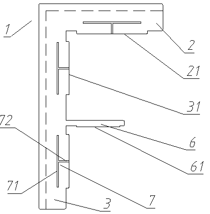
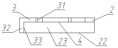
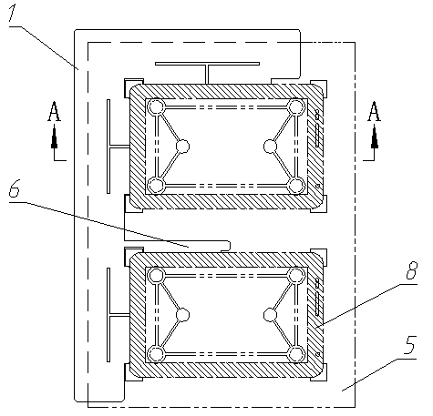
[0016] An embodiment of the screen printing positioning fixture of the present invention Figure 1~Figure 5 As shown, the screen printing positioning fixture for the display screen includes a clamp body 1, which includes a transverse positioning plate 2 and a longitudinal positioning plate 3 connected in an L-shaped butt connection, and the transverse positioning plate 2 and the longitudinal positioning plate 3 are both It has a lower surface 4 for mating and fitting with the upper surface of the corresponding plate loading jig. The butt of the horizontal positioning plate 2 and the vertical positioning plate 3 has an inner corner corresponding to the corner of the display screen 8. The horizontal positioning plate 2 and the longitudinal positioning plate 3 both have inner sides connected to the inner corners and perpendicularly connected to the lower surface 4. The inner side of the transverse positioning plate 2 includes a transverse edge corresponding to the display screen 8 ...


PUM


Abstract

The invention relates to a display screen silk-screen printing positioning clamp. The display screen silk-screen printing positioning clamp comprises a transverse positioning plate and a longitudinal positioning plate, wherein the transverse positioning plate and the longitudinal positioning plate are connected in an L-shaped butt-joint mode. The transverse positioning plate and the longitudinal positioning plate are respectively provided with a lower surface matched with the upper surface of a disc installation clamp in an attached mode. The positions where the transverse positioning plate and the longitudinal positioning plate are in butt-joint are provided with inner angles corresponding to corners of a display screen. The transverse positioning plate and the longitudinal positioning plate are further provided with inner side faces perpendicularly connected with the lower surfaces and connected with the inner angles. The inner side face of the transverse positioning plate comprises a longitudinal positioning face used for being in stoppage fit with a transverse edge corresponding to the display screen in the longitudinal direction and being in pilot fit with in the vertical direction. The inner surface of the longitudinal positioning plate comprises a corresponding transverse positioning face. The clamp further comprises a positioning structure used for enabling the clamp to be positioned on the corresponding disc installation clamp so as to enable the transverse positioning face and the longitudinal positioning face to be respectively flush with a transverse groove wall face and a longitudinal groove wall face of a groove corresponding to the disc installation clamp in a coplane mode. The display screen silk-screen printing positioning clamp can play an auxiliary positioning role in loading so as to facilitate loading.

Description

Technical field [0001] The invention relates to a screen printing positioning fixture for a display screen. Background technique [0002] Some electronic products with display screens, such as mobile phones, require a screen printing process to print patterns on the display glass during the production process. In this process, the display screen needs to be carried by a display screen printing and mounting fixture. For example, the glass loading fixture disclosed in the Chinese patent with application number 201220330634.X and authorized announcement number 202656598U is a plate loading fixture, including a clamp body, and the upper surface of the clamp body is provided with a gap for the glass in the thickness direction The grooves are matched and embedded in the grooves. The grooves have groove walls connected perpendicularly to the upper surface of the clamp body. During printing, the display screen needs to be loaded into the grooves on the plate loading fixture to be positio...

Claims


Application Information

Patent Timeline
Patent Type & Authority Applications(China)
IPC IPC(8): B41F15/18
Inventor 王新彬
Owner 新乡市天光科技有限公司
Why Eureka
Try Eureka