Cable pressure resistant test device and cable pressure resistant test method
A withstand voltage test device and a withstand voltage test technology, applied in the direction of testing the dielectric strength, etc., can solve the problems of high electric field strength, waste of materials, large discharge capacity, etc., and achieve the effect of uniform charge distribution and avoid breakdown phenomenon
Active Publication Date: 2013-10-02
宁联电缆集团有限公司
View PDF5 Cites 3 Cited by
- Summary
- Abstract
- Description
- Claims
- Application Information
AI Technical Summary
Problems solved by technology
[0003] However, the current test method has the following problems in actual operation: the two ends of the cable are respectively placed in two test tubes filled with insulating silicone oil. A large amount of charge accumulates near the cross-section of the end, causing the local electric field strength near the cross-section to be too large, making it easy to be broken down near the cross-section, causing the test to be interrupted when it is not completed normally
Method used
View moreImage
Smart ImageViewing Examples

Examples
 PUM
 Abstract
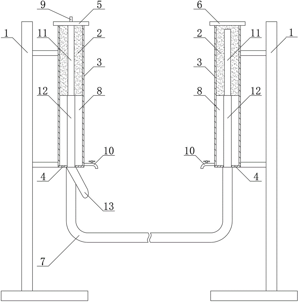
The invention provides a cable pressure resistant test device and a cable pressure resistant test method. The cable pressure resistant test device comprises a pair of test pipes which are vertically arranged on an insulation bracket; plugging structures are arranged at both the lower ends of the test pipes; each plugging structure comprises a cable conductor socket matched with the semi-conductor layer of a cable conductor; a metal electrode cover is arranged at the upper end of one test pipe; an insulating cover is arranged at the upper end of the other test pipe; the metal electrode cover comprises a cover body and an electrode joint; the cover body is arranged at the upper end of a corresponding test pipe; the electrode joint is arranged on the cover body. As the cable conductor socket is arranged at the bottom end of the test pipe, the cable conductor is inserted into the test pipe through the cable conductor socket from the bottom up, different cable layers of the cable conductor correspond to different liquid test media in the test pipe, and cable pressure resistant tests such as a quadruple four-hour cable pressure resistant test can be carried out.
Description
technical field [0001] The invention relates to a test device and a test method, in particular to a cable withstand voltage test device and a cable withstand voltage test method used in a power frequency AC withstand voltage test. Background technique [0002] Power frequency AC withstand voltage test is the most direct method to identify the insulation strength of wires and cables. It is of decisive significance for judging whether the wires and cables are put into operation, and it is also an important means to ensure the insulation level of wires and cables and avoid insulation accidents. The cable withstand voltage test has higher requirements on the cable insulation performance, and it is also the best method to test the cable insulation performance. [0003] However, the current test method has the following problems in actual operation: the two ends of the cable are respectively placed in two test tubes filled with insulating silicone oil. A large amount of charge ac...
Claims
Login to View More Application Information
Patent Timeline
 IPC IPC(8): G01R31/12
Inventor 张高磊张之明胡滨
Owner 宁联电缆集团有限公司
Features
- R&D
- Intellectual Property
- Life Sciences
- Materials
- Tech Scout
- Unparalleled Data Quality
- Higher Quality Content
- 60% Fewer Hallucinations
Learn More Browse by: Latest US Patents, China's latest patents, Technical Efficacy Thesaurus, Application Domain, Technology Topic, Popular Technical Reports.
© 2025 PatSnap. All rights reserved.Legal|Privacy policy|Modern Slavery Act Transparency Statement|Sitemap|About US| Contact US: help@patsnap.com