Cage landing door structure
A hanging cage and landing door technology, which is applied in the field of construction machinery accessories, can solve the problems of inconvenient replacement of landing door locks, and achieve the effect of convenient replacement and installation operation and correct installation position
- Summary
- Abstract
- Description
- Claims
- Application Information
AI Technical Summary
Problems solved by technology
Method used
Image
Examples
Embodiment 1
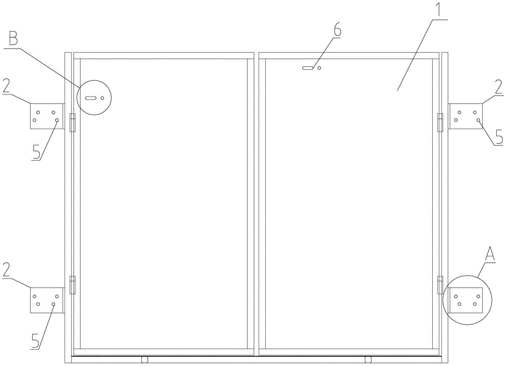
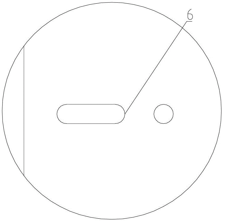
[0022] In the following, in conjunction with the accompanying drawings, the cage floor door structure of the present invention will be further described. Such as figure 1 , figure 2 , image 3 As shown, the cage landing door includes a landing door 1 and a wall attached frame 3. The landing door 1 is arranged on the wall attached frame 3, and the height of the landing door 1 is 1 / 2 to 2 / 3 of the height of the cage opening After the landing door 1 is closed, the opening of the landing door 1 cannot be completely closed, which improves the light transmission and ventilation performance inside the cage. The landing door 1 includes a connecting edge and a closing edge. The landing door 1 is provided with a detection landing door 1 state of the electrical switch and the landing door lock used to lock the landing door 1, because the cage landing door is not allowed to be opened casually during the operation of the cage, so the landing door 1 is provided with the landing door 1 and th...
Embodiment 2
[0024] Such as figure 1 , figure 2 , Figure 4 As shown, the cage landing door includes a landing door 1 and a wall attached frame 3. The landing door 1 is arranged on the wall attached frame 3, the landing door 1 includes a connecting edge and a closing edge, and the connection of the landing door 1 A connecting piece 2 with an L-shaped cross-section is provided between the side and the wall attachment frame 3, and the connecting piece 2 is connected with the wall attachment frame 3 by a hoop 4, and the connecting piece 2 and the landing door 1 are connected by welding , The connecting member 2 is provided with two sets of matching holes 5 that can be matched with the hoops 4 of different specifications, and the midpoint of the center line of the same set of matching holes 5 is located at the same center line of the other sets of matching holes 5 On a straight line, that is, the midpoint of the center line of the first group of mating holes 5 and the midpoint of the second gr...
PUM
 Abstract
Description
Claims
Application Information
 - R&D
- Intellectual Property
- Life Sciences
- Materials
- Tech Scout
- Unparalleled Data Quality
- Higher Quality Content
- 60% Fewer Hallucinations
Browse by: Latest US Patents, China's latest patents, Technical Efficacy Thesaurus, Application Domain, Technology Topic, Popular Technical Reports.
© 2025 PatSnap. All rights reserved.Legal|Privacy policy|Modern Slavery Act Transparency Statement|Sitemap|About US| Contact US: help@patsnap.com


