
Key structure

A key and keycap technology, applied in electrical components, electrical switches, circuits, etc., can solve problems such as size reduction, complex assembly operations, and limited lifting characteristics.

Active Publication Date: 2013-09-25
DARFON ELECTRONICS (SUZHOU) CO LTD +1
View PDF4 Cites 13 Cited by
  • Summary
  • Abstract
  • Description
  • Claims
  • Application Information

AI Technical Summary

Problems solved by technology

However, as the requirements for thinner and thinner become higher and higher, the conventional button structure is limited by the volume of the elastic body and the lifting characteristics of the scissor-type support, and has reached the limit of size restriction.
In addition, when the scissor support is assembled, the four supporting ends of the scissor support must be connected to the keycap and the bottom plate respectively, which makes the assembly work very complicated

Method used


Image

  • Key structure
  • Key structure
  • Key structure

Examples


Embodiment Construction

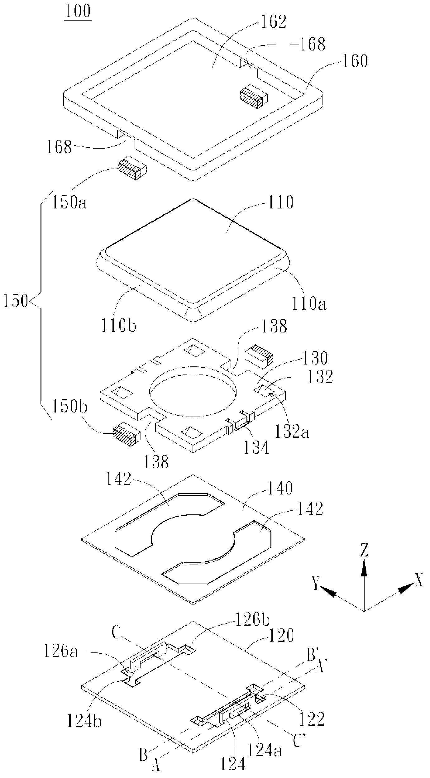
[0028] The present invention provides a button structure, which can be applied to any push-type input device, such as a keyboard, so as to effectively reduce the height of the buttons, simplify assembly complexity and satisfy the user's pressing habits. The structure and operation of each element of the key structure according to the embodiment of the present invention will be described in detail below with reference to the drawings.

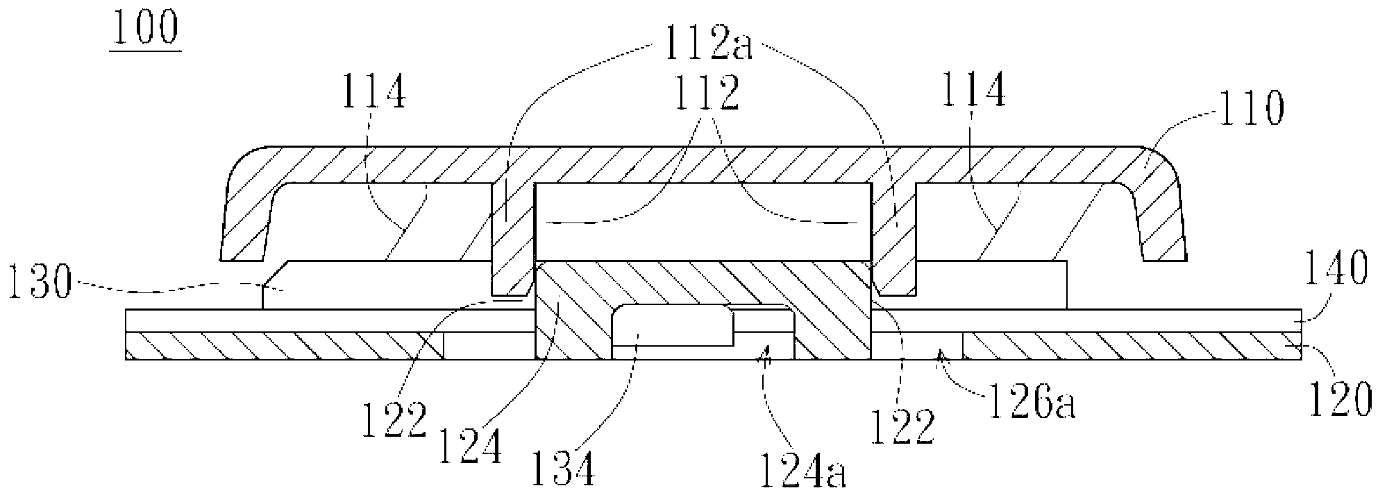
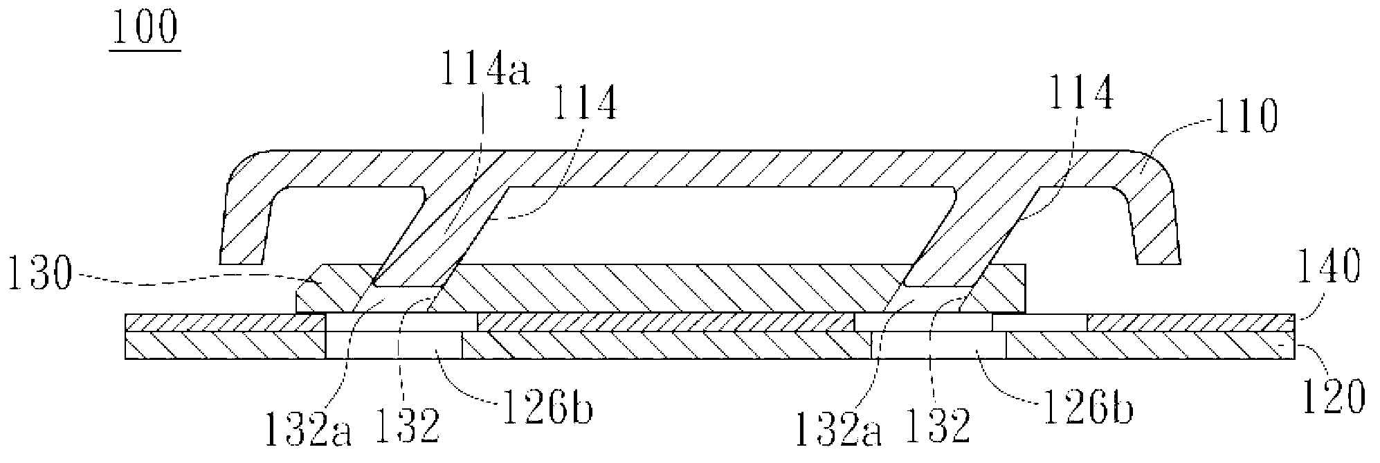
[0029] figure 1 It is an exploded view of the button structure according to an embodiment of the present invention, Figure 2A for along figure 1 The A-A' line is the cross-sectional view of the key structure after assembly, Figure 2B for along figure 1 The B-B' line is the cross-sectional view of the key structure after assembly, while Figure 2C for along figure 1 The C-C' line is the cross-sectional view of the key structure after assembly. like figure 1 and Figures 2A-2C As shown, the button structure 100 of the present invention i...


PUM


Abstract

The invention relates to a key structure, the key structure comprises a key cap, a base plate, a sliding part and a resetting mechanism. The key cap is provided with a first perpendicular combination mechanism and a first perpendicular / horizontal switching mechanism, the base plate is provided with a second perpendicular combination mechanism, and the sliding part is provided with a second perpendicular / horizontal switching mechanism. Due to the fact that the key cap is limited by combination between the second perpendicular combination mechanism and the first perpendicular combination mechanism, the key cap can only move along a Z-axis relative to the base plate. Due to combination between the second perpendicular / horizontal switching mechanism and the first perpendicular / horizontal switching mechanism, when the key cap receives a pressing action to move towards the base plate along the Z-axis, the sliding part correspondingly carries out first movement, and the sliding part at least has positive-direction displacement along the X-axis. When the pressing action is released, the resetting device provides horizontal recovery force to enable the sliding part to carry out second movement, and the sliding part at least has negative-direction displacement along the X-axis so as to drive the key cap to move far away from the base plate along the Z-axis. The key structure can remarkably reduce the integrated height, and can meet the requirement for pressing section feels of a user.

Description

technical field [0001] The present invention relates to a button structure. Specifically, the present invention relates to a button structure in which the keycap is vertically displaced along the Z axis, the guide slides on the XY plane, and the guide is pushed horizontally by magnetic attraction. Background technique [0002] The conventional button structure usually utilizes an elastic body to provide the power for the keycap to rise and return after being pressed, and uses a scissor-like support to support the stability of the keycap's lifting. However, as the requirement for thinner and thinner is getting higher and higher, the conventional button structure is limited by the volume of the elastic body and the lifting characteristics of the scissor-type supporting member, so the size limit has been reached. In addition, when the scissor support is assembled, the four supporting ends of the scissor support must be respectively connected to the keycap and the bottom plate, ...

Claims


Application Information

Patent Timeline
Patent Type & Authority Applications(China)
IPC IPC(8): H01H13/14
Inventor 江滋邦
Owner DARFON ELECTRONICS (SUZHOU) CO LTD
Learn More