Experiment device for regulating engine different angles in variable valve different lifting method

A technology of different lifts and experimental devices, which is applied in the direction of internal combustion engine testing, etc., can solve problems such as single tumble mode, increased vortex, and combustion deterioration

Active Publication Date: 2013-09-25
MILITARY TRANSPORTATION UNIV PLA
View PDF8 Cites 6 Cited by
  • Summary
  • Abstract
  • Description
  • Claims
  • Application Information

AI Technical Summary

Problems solved by technology

[0002] The four-valve engine has gradually been widely used due to its obvious advantages in improving combustion compared with the two-valve engine. However, due to the symmetrical arrangement of the double intake port structure and the two cam profiles that drive the intake valves, the four-valve engine is almost the same. The two intake valves open to the same degree at the same time, so that the intake velocity and intake air volume of the two intake valves are the same at the same time, and the rotating airflow in the cross-sectional direction of the cylinder block cancels each other out, and the overall movement of the air in the cylinder is expressed as a single longitudinal direction. In the tumble mode, there is almost no vortex, and the inability of both vortex and tumble to exist at the same time is an important factor that causes poor mixture formation and poor combustion
However, no matter whether the lift of the two intake cams is reduced at the same time or the lift of one of the intake cams is reduced in the above structure, the vortex phase obtained is still equivalent to partially closing two valves or one of the valves, and its flow capacity is higher than that of the double intake cam. The valve (or intake port) is fully open, and the high vortex intensity is obtained at the expense of the intake air flow. It is only suitable for low speed conditions. At high speeds, the intake air flow is insufficient. Two intake valves must be fully opened to ensure intake air. flow, the above mechanism cannot be used to increase the vortex
[0005] The Chinese patent with the application number 200510013859.7 discloses a device and a related method for different lifts of intake valves of internal combustion engines. It proposes a different lift technology for intake valves to solve the above technical problems. The requirements for vortex motion and flow coefficient are different under load. It is necessary to conduct tests according to the working conditions to determine the different angles of different lifts of the intake valves under different working conditions. The technical solution disclosed in this patent cannot adjust the different generation angles. Therefore, it is necessary to invent a set of engine variable intake valve different lift different angle experimental adjustment device

Method used


Image

  • Experiment device for regulating engine different angles in variable valve different lifting method
  • Experiment device for regulating engine different angles in variable valve different lifting method
  • Experiment device for regulating engine different angles in variable valve different lifting method

Examples


Embodiment

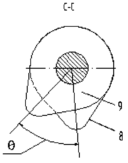
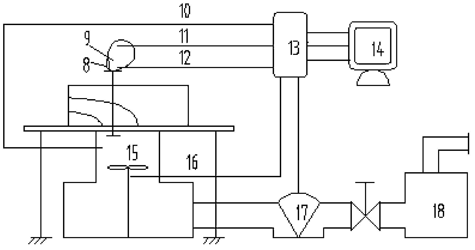
[0017] Such as figure 1 , 2 Shown is the experimental device for adjusting different lifts and different angles of variable intake valves of the engine, which includes a screw rod 1, an inner and outer gear sleeve rod 3, a guide sleeve 4, an outer camshaft 5, an inner camshaft 7, and a phase advance cam 8 and a phase lagging cam 9; the left end of the screw rod 1 is square, the right end is equipped with a connecting plate, and its outer periphery is equipped with a screw nut 2 matched with it;

[0018] The left end of the internal and external gear sleeve rod 3 has a groove, and the right end has internal and external teeth; the left end of the external camshaft 5 has internal teeth, and the right end is connected to the phase advance cam 8; a camshaft is installed below the external camshaft 5 Angle adjustment handle 6, so that adjust the angle of rotation of outer camshaft 5. The left end of the internal camshaft 7 has external teeth, and the right end is connected to the...


PUM


Abstract

The invention discloses an experiment device for regulating different angles in a variable valve different lifting method. According to the device, a pair of air inlet cams of each cylinder can produce continuously changing different angles, so the valve lifting difference changes, eddy currents are produced and regulated, and a different angle experiment regulation system is provided for researching influences of the variable valve different lifting method on flowing characteristics of air in cylinders of an engine.

Description

technical field [0001] The invention relates to the technical field of engines, in particular to an experimental device for adjusting different lifts and different angles of variable intake valves of engines. Background technique [0002] The four-valve engine has gradually been widely used due to its obvious advantages in improving combustion compared with the two-valve engine. However, due to the symmetrical arrangement of the double intake port structure and the two cam profiles that drive the intake valves, the four-valve engine is almost the same. The two intake valves open to the same degree at the same time, so that the intake velocity and intake air volume of the two intake valves are the same at the same time, and the rotating airflow in the cross-sectional direction of the cylinder block cancels each other out, and the overall movement of the air in the cylinder is expressed as a single longitudinal direction. In the tumble flow mode, there is almost no vortex flow...

Claims


Application Information

Patent Timeline
IPC IPC(8): G01M15/04
Inventor 刘瑞林张士强刘伍权董素荣戴俊周广猛
Owner MILITARY TRANSPORTATION UNIV PLA
Why Eureka
Try Eureka