Runner screw guide type drive impeller

A runner and screw technology, applied in propellers, rotating propellers, transportation and packaging, etc., can solve the problems of hindering high-speed driving, upper limit, resistance shock wave, etc., and achieve the effect of changing energy consumption and increasing the upper limit of driving speed

Active Publication Date: 2016-03-30
马勤荣
View PDF5 Cites 0 Cited by
  • Summary
  • Abstract
  • Description
  • Claims
  • Application Information

AI Technical Summary

Problems solved by technology

[0002] At present, the commonly used underwater runner is driven by a propeller at the rear end of the runner. This driving method is to use the inclined plane of the propeller blade to force the external medium behind the blade to generate pressure to push the runner forward, so that , with the increase of running speed, the water (liquid) external medium pressure at the front end of the running body will continue to increase, and the negative pressure at the rear end of the running body will also increase at the same time, and its operation can only be reversed at the front and rear ends When the pressure difference is carried out, the reaction force becomes larger and larger, and the forward resistance and driving difficulty continue to increase. The energy consumed by the same distance will increase due to the increase in speed. The forward resistance is proportional to the square of the speed. Vulnerable to the upper limit of speed
[0003] At present, the propulsion of the commonly used air runners is also at the rear end or on both sides. Although the ram propulsion can obtain a strong propulsion pressure, the pressure of the external medium at the front end that increases with the speed cannot be overcome after all. Extremely energy-consuming when traveling at supersonic speeds and generate powerful resistance shock waves, hindering high-speed driving

Method used


Image

  • Runner screw guide type drive impeller
  • Runner screw guide type drive impeller
  • Runner screw guide type drive impeller

Examples


Embodiment Construction

[0016] The present invention will be described in further detail below in conjunction with the accompanying drawings.

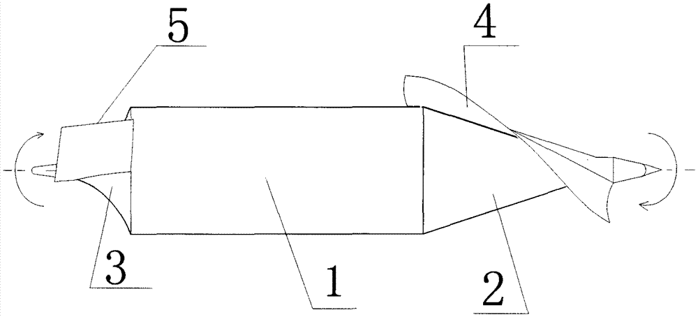
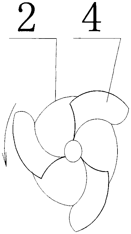
[0017] The present invention is a spiral pressure-guided driving impeller for a runner, which includes a runner 1 and a front impeller 2; the front impeller 2 for dredging the pressure generated by the external medium due to the speed is installed on the outside of the front cone of the runner 1, The front blade 4 is installed on the front impeller 2 outside the front vertebral body of the runner 1. The front blade 4 is spirally arranged on the cone surface of the front impeller 2. The front end of the front blade 4 is biased to the direction of rotation, and the surface of the front blade 4 is groove-shaped. , the direction of the groove faces the direction of rotation of the front impeller 2, the line connecting the inner and outer edges of the front blade 4 is perpendicular to the axis of the runner 1, the shape of the front blade 4 is twisted, and the fron...


PUM


Abstract

The invention discloses a spiral pressure-guiding drive impeller of a runner. The spiral pressure-guiding drive impeller comprises a runner and a front impeller; the front impeller for guiding pressure caused by the speed of an external medium is mounted on the outer side of a cone part at the front end of the runner; a front blade is mounted on the front impeller on the outer surface of the cone part at the front end of the runner and is in a spiral arrangement on the conical surface of the front impeller; the front end of the front blade deflects to a rotation direction; the surface of the front blade takes the shape of a groove which faces the rotation direction of the front impeller; the connecting line of the edges of the inner side and the outer side of the front blade are perpendicular to the axis of the runner; the front blade takes the shape of a fried dough twist. The spiral pressure-guiding drive impeller can change a reverse pressure difference produced by the conventional runner which runs at a high speed, improves the condition that a forward resistance increases with the squares of speeds, guides the immediate pressure of the external medium at the front end of the runner when the runner needs to speed up, acquires forward thrust by virtue of the guiding action, and meets the requirements in increasing the upper limit of the speed of the conventional runner.

Description

technical field [0001] The invention belongs to the driving field of underwater (such as submarines, etc.) and air (such as aircraft, etc.) runners, in particular to a spiral pressure-guided driving impeller of the runner. Background technique [0002] At present, the commonly used underwater runner is driven by a propeller at the rear end of the runner. This driving method is to use the inclined plane of the propeller blade to force the external medium behind the blade to generate pressure to push the runner forward, so that , with the increase of running speed, the water (liquid) external medium pressure at the front end of the running body will continue to increase, and the negative pressure at the rear end of the running body will also increase at the same time, and its operation can only be reversed at the front and rear ends When the pressure difference is carried out, the reaction force becomes larger and larger, and the forward resistance and driving difficulty conti...

Claims


Application Information

Patent Timeline
Patent Type & Authority Patents(China)
IPC IPC(8): B63H1/14B64C11/00
Inventor 马勤荣
Owner 马勤荣
Why Eureka
Try Eureka