Molded electric motors and air conditioners

A motor and molding technology, which is used in the manufacture of motor generators, motor components, and mechanical energy control. It can solve problems such as unable to cope with specification changes and rotor installation, and achieve the effect of improving electrical corrosion resistance and product quality.

Inactive Publication Date: 2015-11-25
MITSUBISHI ELECTRIC CORP
View PDF8 Cites 0 Cited by
  • Summary
  • Abstract
  • Description
  • Claims
  • Application Information

AI Technical Summary

Problems solved by technology

Therefore, there is a problem that, for example, in the case of a long shaft, the rotor cannot be easily mounted on the shaft, and it may not be possible to cope with specification changes

Method used


Image

  • Molded electric motors and air conditioners
  • Molded electric motors and air conditioners
  • Molded electric motors and air conditioners

Examples


Embodiment approach

[0090] (summary)

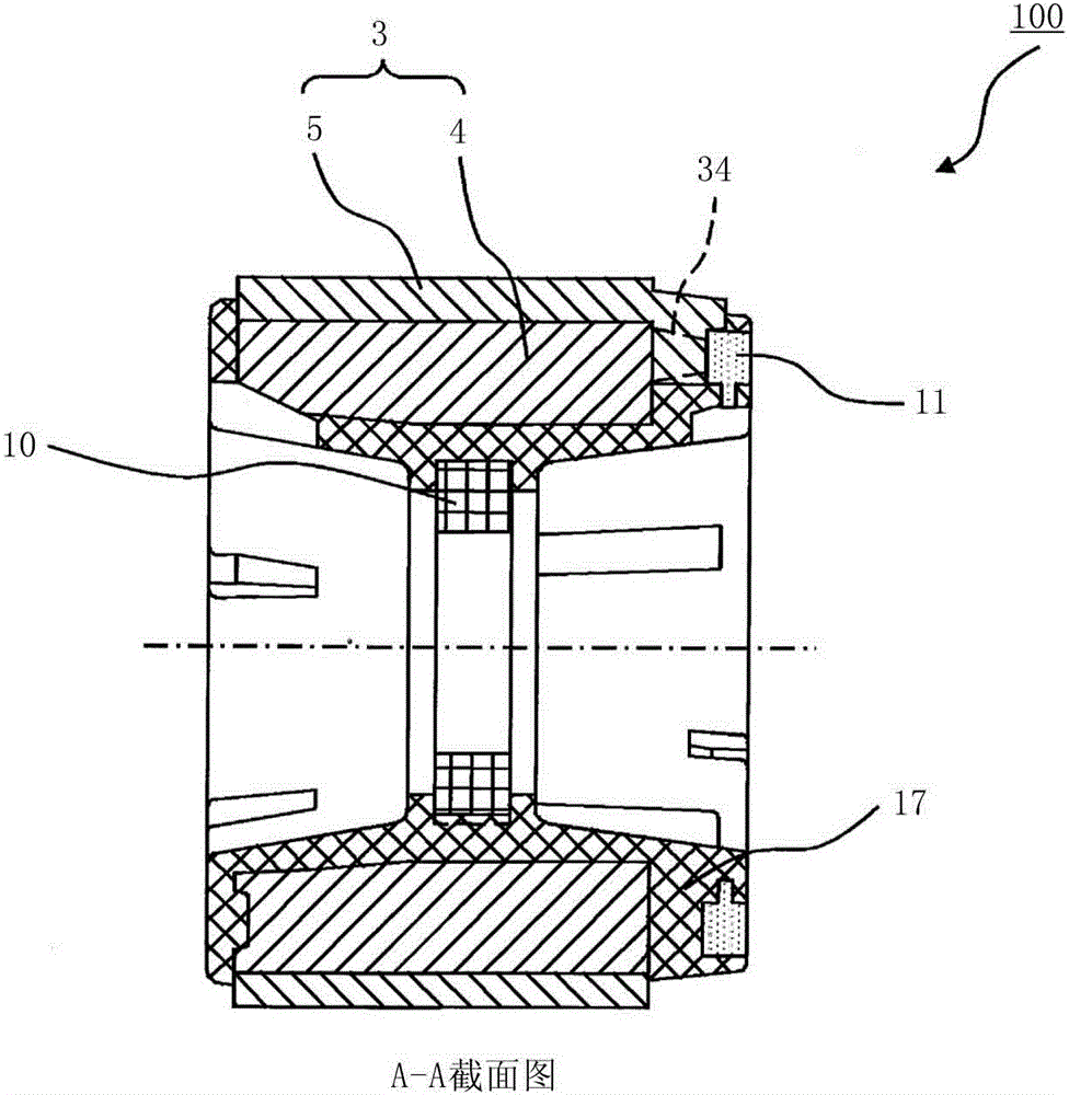
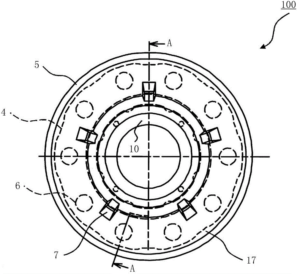
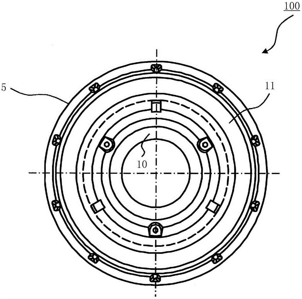
[0091] The rotor of the electric motor according to this embodiment is characterized in that the length (or diameter) of the shaft and the position of the rotor on the shaft can be arbitrarily selected. For example, the rotor of a motor with a load (fan, etc.) attached to only one end of the shaft, since the shaft is short and the position of the rotor on the shaft is determined, the rotor magnet, the magnet for position detection, and the shaft can be integrally molded with resin .

[0092] However, when the shaft is long, when the rotor magnet, the position detection magnet, and the shaft are integrally molded with resin, the length of the shaft is limited by the amount of mold opening during resin molding and cannot be of any length.

[0093] Therefore, different molds are required in case the position of the rotor on the shaft varies.

[0094] Therefore, in this embodiment, in addition to the rotor magnet and the magnet for position detection, a short ...


PUM


Abstract

A mold motor 400 includes a mold stator 350, a rotor 200, and a bracket 440. The mold stator 350 includes a first bearing housing section formed of thermosetting resin, one bearing 410 of the rotor 200 fitting in one end in an axial direction of the first bearing housing section, an opening section formed at an end on the opposite side of the bearing housing section, and a bracket press-fitting section formed near the opening section and having a diameter larger than a stator inner diameter. The bracket 440 includes a bracket resin section configuring a second bearing housing section in which the other bearing 410 of the rotor 200 fits and a bracket sheet metal section press-fit into the bracket press-fitting section of the mold stator 350. In the bracket 440, the bracket resin section and the bracket sheet metal section are integrally molded.

Description

technical field [0001] The present invention relates to a molded motor in which a bracket is composed of a resin part and a sheet metal part, is electrically insulated from a bearing, and has improved electrical corrosion resistance of the bearing. Moreover, it is related with the air conditioner which mounted this molded motor in the blower. Background technique [0002] For the rotor of an electric motor, a proposal has been made in which a permanent magnet is provided with a cylindrical sleeve, and the shaft is fixed to the sleeve to form the rotor. By injecting ferrite resin magnets and the like to form permanent magnets, permanent magnets and bushings can be assembled at the same time during injection molding of permanent magnets, reducing assembly man-hours. In addition, even when the shape and length of the shaft are different, the permanent magnet molded together with the sleeve can be used in one type of mold, so it is effective in improving productivity (for examp...

Claims


Application Information

Patent Timeline
Patent Type & Authority Patents(China)
IPC IPC(8): H02K5/16H02K5/08
CPCH02K5/02H02K1/276H02K5/1732H02K7/08H02K15/03H02K15/12H02K5/04
Inventor 山本峰雄坂廼边和宪石井博幸麻生洋树尾村和也竹内康真柴山胜己望月均
Owner MITSUBISHI ELECTRIC CORP
Why Eureka
Try Eureka