
Swivel with or for hydrant manifold industrial fire fighting

A hydrant water separator and fire-fighting technology, which is applied in the field of rotary fire hydrant water separators, can solve the problems of increased waste costs and increased diameter requirements

Inactive Publication Date: 2013-09-18
WILLFIRE HC
View PDF5 Cites 3 Cited by
  • Summary
  • Abstract
  • Description
  • Claims
  • Application Information

AI Technical Summary

Problems solved by technology

[0009] While the industrial fire protection industry has historically suffered from wasted hose and duplication of hydrants due to fixed hydrant manifolds, as the diameter requirements for service pipes and hoses increase, so does the cost of waste

Method used


Image

  • Swivel with or for hydrant manifold industrial fire fighting
  • Swivel with or for hydrant manifold industrial fire fighting
  • Swivel with or for hydrant manifold industrial fire fighting

Examples


Embodiment Construction

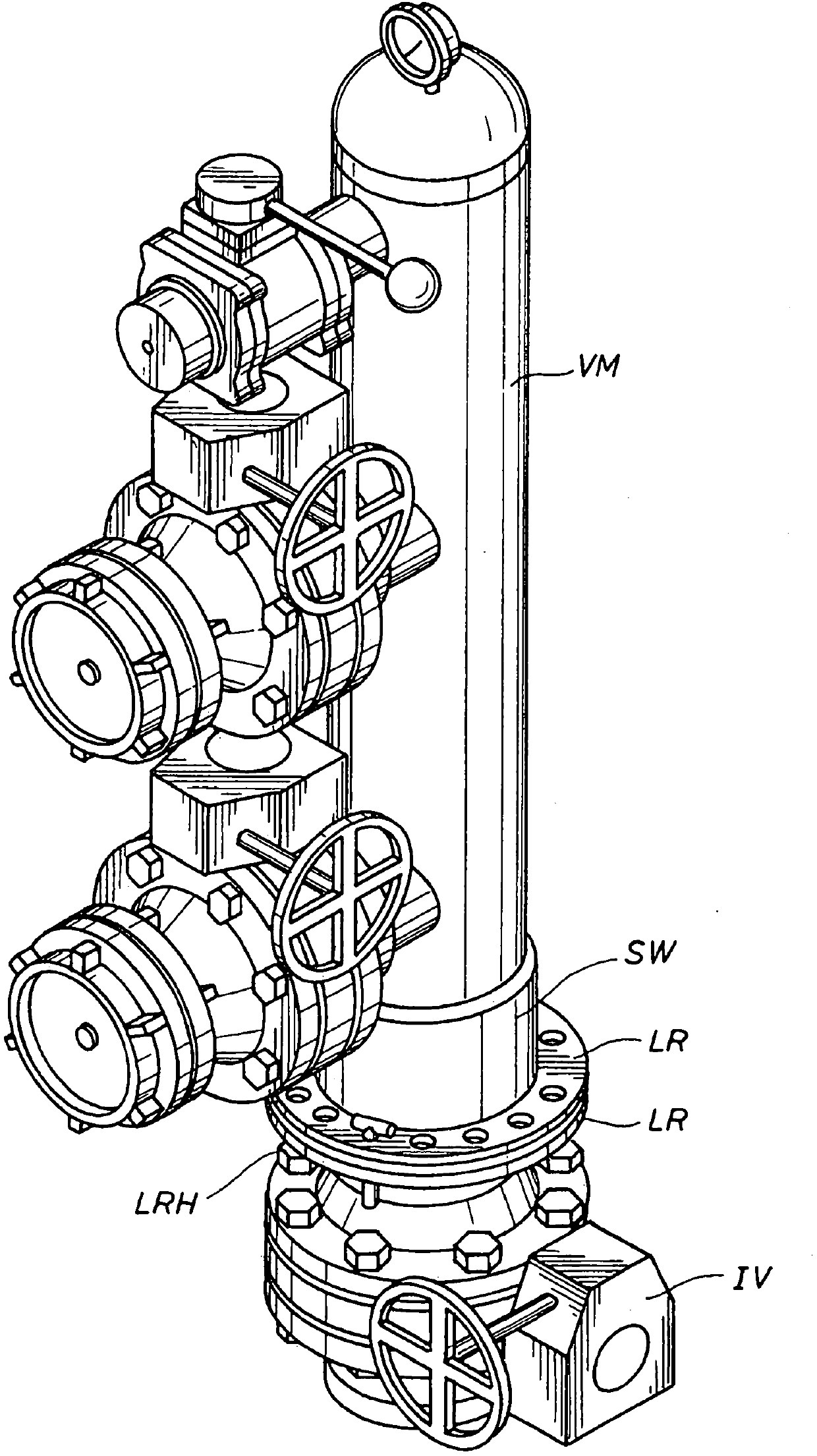
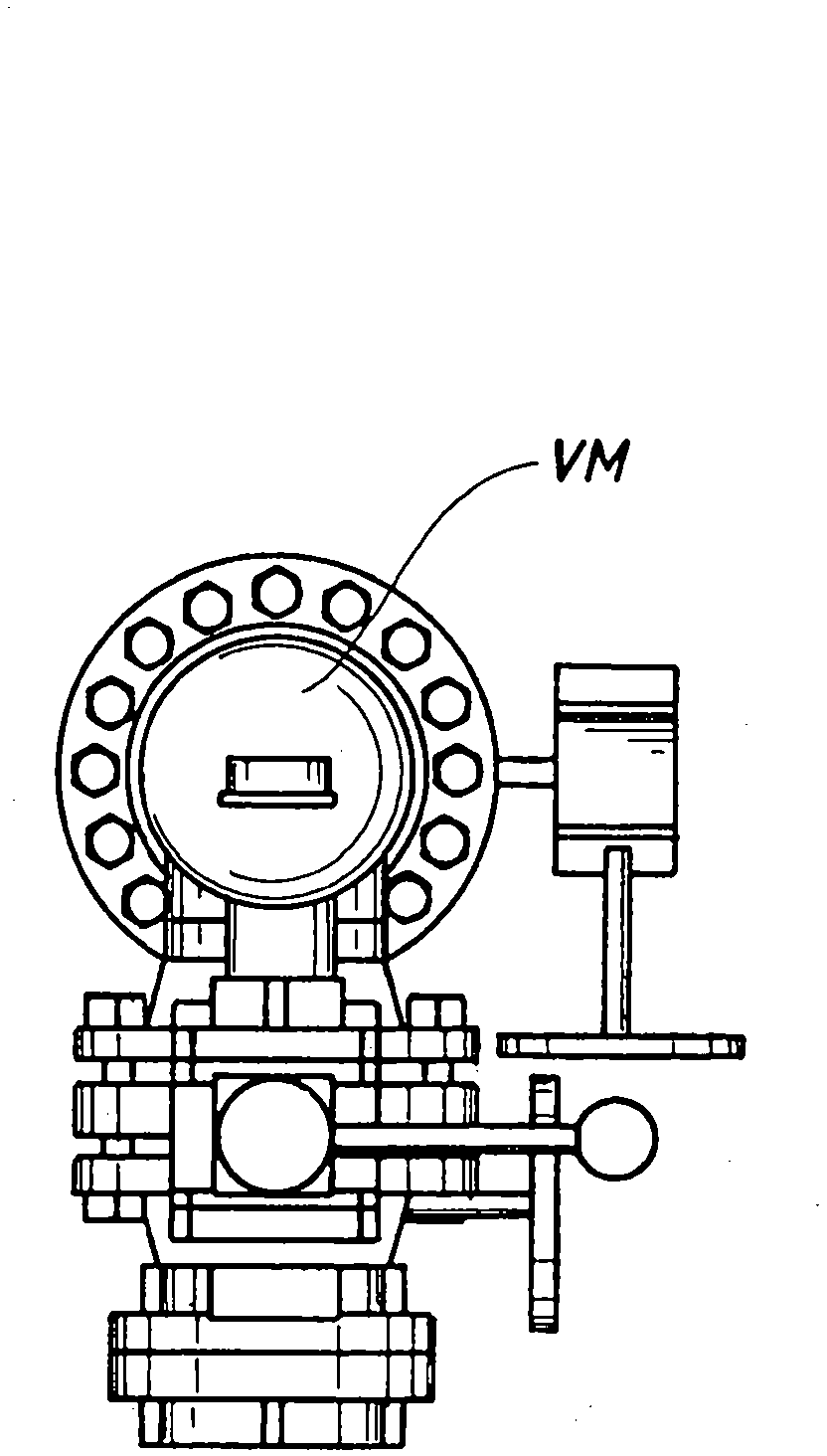
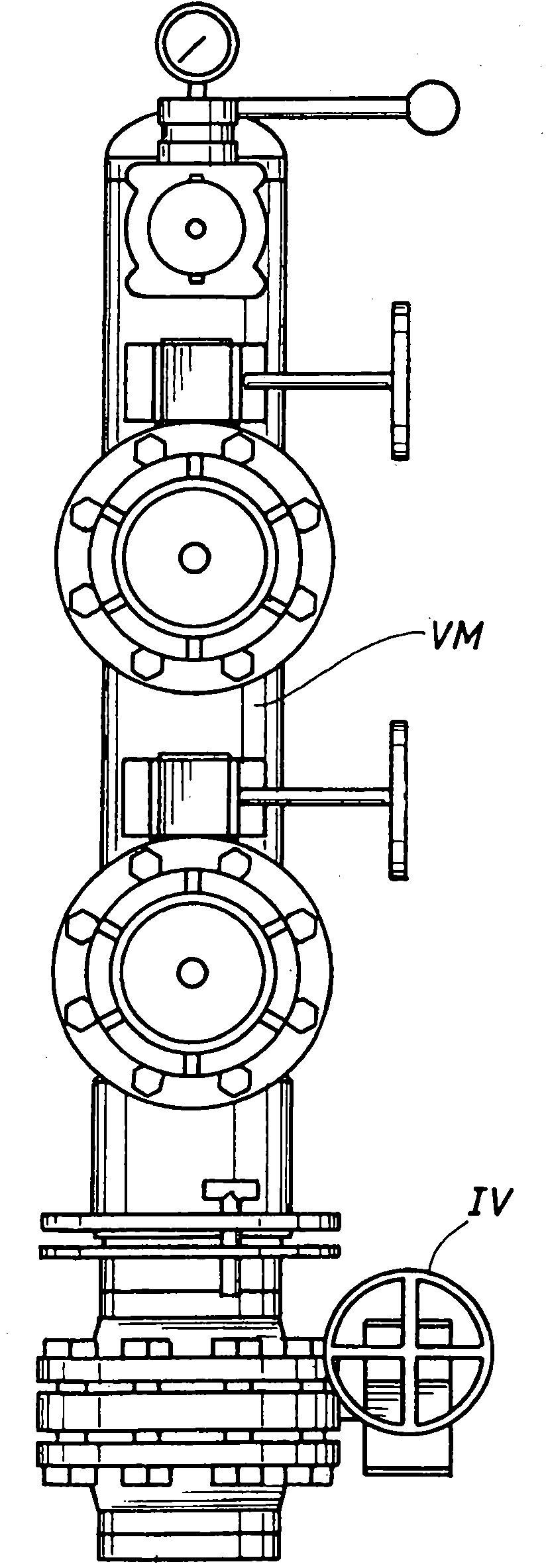
[0084] As shown in Figures 1-8, the preferred swivel embodiment of the present invention includes 316 stainless steel sleeves FS and MS and ball bearings SB. Stainless steel sleeves are preferably heat treated and annealed. In a preferred embodiment, the races RSSB of the bearing rings for at least two ball bearings SB are ground, half forming a female sleeve FS and half forming a male sleeve MS, wherein in the female The sleeve is provided with a port P for insertion of the ball bearing SB. Preferably at least one grease nipple GF is provided to maintain proper lubrication of the area between male MS and female sleeve FS and around ball bearing SB.

[0085] An external debris seal location DSL is preferably provided for a debris seal, such as an O-ring, which is provided in a suitable notch between the male and female bushings. In a preferred embodiment, a simple O-ring has been shown to prevent debris from entering the area between the male and female sleeves from the outs...


PUM


Abstract

A swivel with, or for, a hydrant manifold for industrial fire fighting comprising a swivel providing an at least 6 inch flow conduit and preferably including mating male and female sleeves of stainless steel and preferably having at least two rings of stainless steel ball bearings and a location for an interior water seal.

Description

[0001] Horizontal references to related applications [0002] This application relates to and claims Serial Nos. 61 / 459,232 and 61 / 464,628 filed on 12 / 9 / 2010 and 3 / 7 / 2011 by the same inventor, respectively, titled "Swivel Hydrant Manifold for Industrial Fire Fighting" and "Swivel With or for Industrial Hydrant Manifold for Industrial Fire Fighting" co-pending application. The contents of both provisional applications are hereby incorporated by reference. technical field [0003] This invention relates to hydrant manifolds for industrial fire protection in factories and facilities, and more particularly to rotary hydrant manifolds (herein "diverters" may include a single port). Background technique [0004] When faced with industrial fire response, fire scene logistics are problems of approximately the same order as equipment-on-hand problems and available personnel problems. [0005] Large fires require large quantities of water, which sometimes require multiple large diam...

Claims


Application Information

Patent Timeline
Patent Type & Authority Applications(China)
IPC IPC(8): E03B9/02
CPCE03B9/04Y10T137/5456E03B9/02
Inventor D·P·威廉姆斯C·R·斯皮尔斯
Owner WILLFIRE HC
Learn More