
Active-control valley fill circuit and control method thereof

A valley-filling circuit and control circuit technology, which is applied to electrical components, high-efficiency power electronic conversion, and output power conversion devices, etc., can solve the problems of lower performance indicators, increased cost, and limited application of valley-filling circuits in the later stage switching power supply. , to achieve the effect of low circuit cost, improved power factor and simple circuit structure

Active Publication Date: 2013-09-18
SHANGHAI LOOALL ELECTRONICS CO LTD
View PDF7 Cites 28 Cited by
  • Summary
  • Abstract
  • Description
  • Claims
  • Application Information

AI Technical Summary

Problems solved by technology

The minimum output voltage of the passive valley-filling circuit is less than half of the peak value of the AC power, which requires that the subsequent switching power supply must adapt to a wider input voltage range, which leads to a decrease in the performance index and an increase in the cost of the subsequent switching power supply, and also leads to The application of this valley filling circuit is limited

Method used


Image

  • Active-control valley fill circuit and control method thereof
  • Active-control valley fill circuit and control method thereof
  • Active-control valley fill circuit and control method thereof

Examples


Embodiment Construction

[0036] The present invention will be further described below in conjunction with the accompanying drawings and specific embodiments.

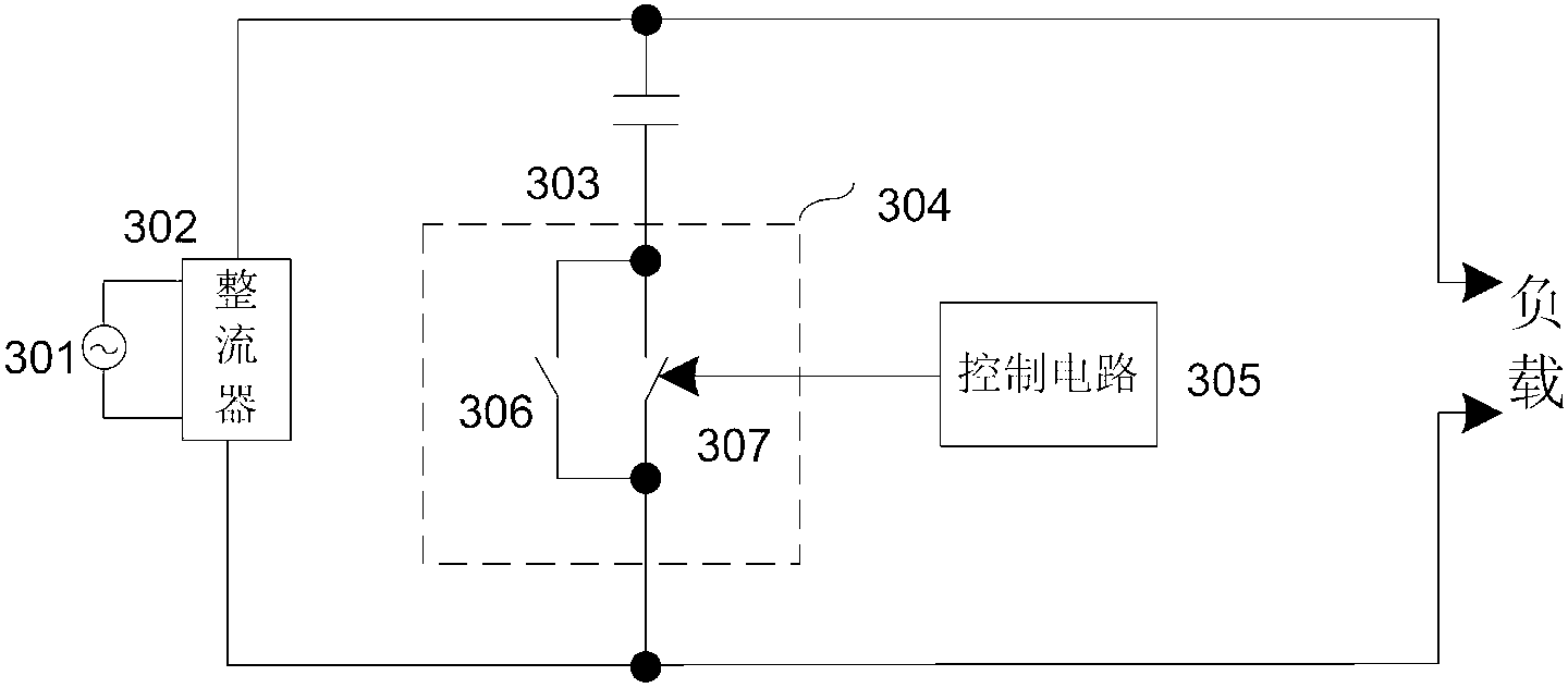
[0037] image 3 It is a basic schematic diagram of the active control valley filling circuit of the present invention, including an AC power supply 301, a rectifier 302, an energy storage capacitor 303, a switch circuit 304, a control circuit 305 and a load. in,

[0038] The alternating current 301 is connected to the input of the rectifier 302, the output of the rectifier 302 is connected to the load, the power terminal of the switch circuit 304 is connected in series with the energy storage capacitor 303 and then connected in parallel to both ends of the output of the rectifier 302, the control terminal of the switch circuit 304 is connected to the control circuit 305, The control circuit 305 is connected to the alternating current for detecting the voltage phase signal of the alternating current;

[0039] The switch circuit includes a char...


PUM


Abstract

The invention discloses an active-control valley fill circuit and a control method thereof which are mainly applied to pre-stage power factor correction and energy accumulation of a switching power supply. The active-control valley fill circuit comprises an alternating-current power supply, a current rectifier, a load, an energy storing capacitor, a switch circuit and control circuit, the alternating-current power supply is connected with an input end of the current rectifier, an output end of the current rectifier is connected with the load, the switch circuit comprises two power ends and a control end of a power channel, the energy storing capacitor is serially connected with the two power ends of the switch circuit and is then parallelly connected with an output end of the current rectifier, and the control end of the switch circuit is connected with the control circuit. According to the control method, by means of presetting threshold voltage, switching between power supplying of the load and energy storing of the energy storing capacitor is realized according to changes of relationships among alternating-current phase position voltage, voltage at two ends of the energy storing capacitor and the threshold voltage. The active-control valley fill circuit has the advantages that a circuit structure is simple, a power factor is improved, output voltage is not higher than alternating-current crest voltage, and the minimum value of the output voltage can be set.

Description

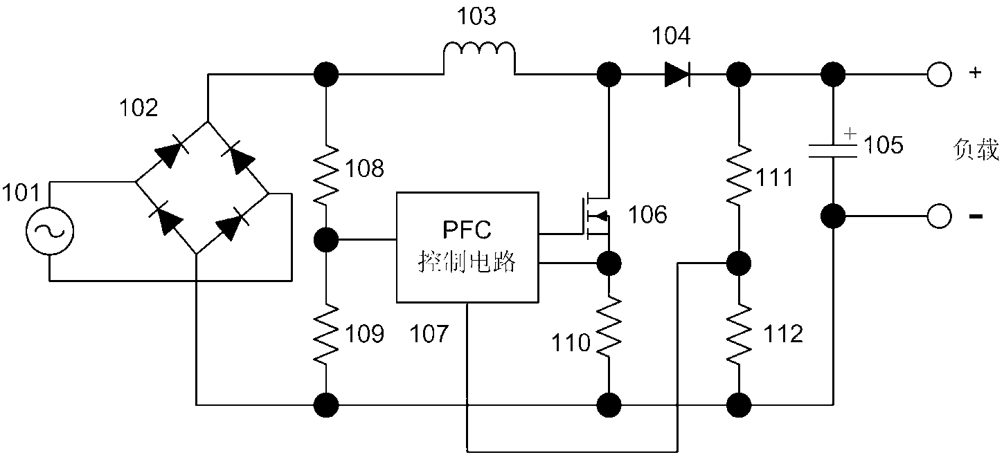
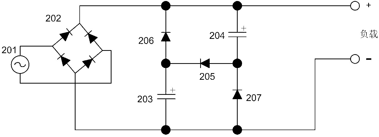
technical field [0001] The invention relates to the field of power supply circuits, in particular to an active-controlled valley-filling circuit and a control method thereof, which are mainly used in pre-stage power factor correction and energy storage of switching power supplies. technical background [0002] At present, switching power supplies have been widely used in various fields of industry and civil use due to their advantages of high efficiency and small size. The switching power supply circuit includes a pre-stage power factor correction circuit and a post-stage switching power supply circuit. The function of the pre-stage power factor correction circuit is to improve the power factor of the electrical equipment, reduce the reactive current, and reduce the pollution of the reactive current to the power grid. There are two main types of common power factor correction circuits at present, as follows: figure 1 and figure 2 shown. [0003] figure 1 It is a current...

Claims


Application Information

Patent Timeline
Patent Type & Authority Applications(China)
IPC IPC(8): H02M1/42
CPCY02B70/10
Inventor 邵蕴奇
Owner SHANGHAI LOOALL ELECTRONICS CO LTD
Learn More