
Capacitance reading circuit of inertia detecting element

An inertial detection and capacitance readout technology, applied in the field of inertial detection, can solve the problems of reducing the signal-to-noise ratio of the measurement circuit and the existence of electric spring effects

Inactive Publication Date: 2013-09-18
INST OF GEOLOGY & GEOPHYSICS CHINESE ACAD OF SCI
View PDF5 Cites 5 Cited by
  • Summary
  • Abstract
  • Description
  • Claims
  • Application Information

AI Technical Summary

Problems solved by technology

[0055] It can be seen from Table 1 that the electric spring effect generated by the driving voltage affects the measurement results. Reducing the driving voltage will reduce the influence of the electric spring effect on the measurement, but at the same time it will reduce the signal-to-noise ratio of the measurement circuit
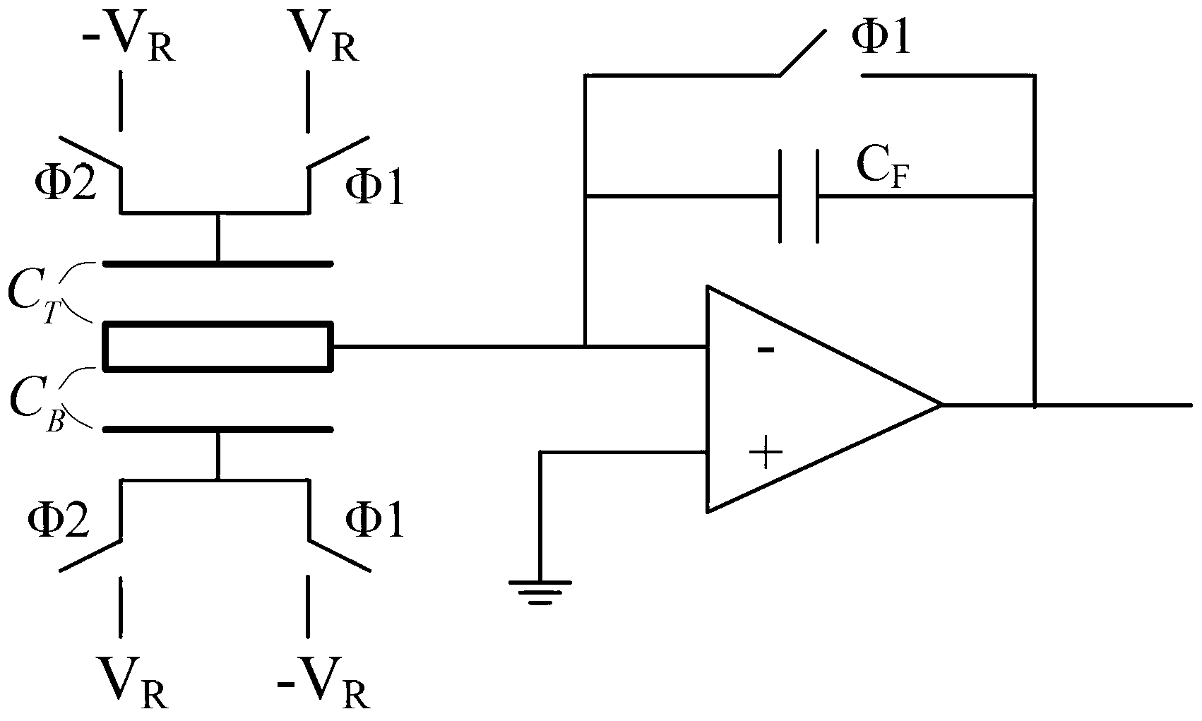
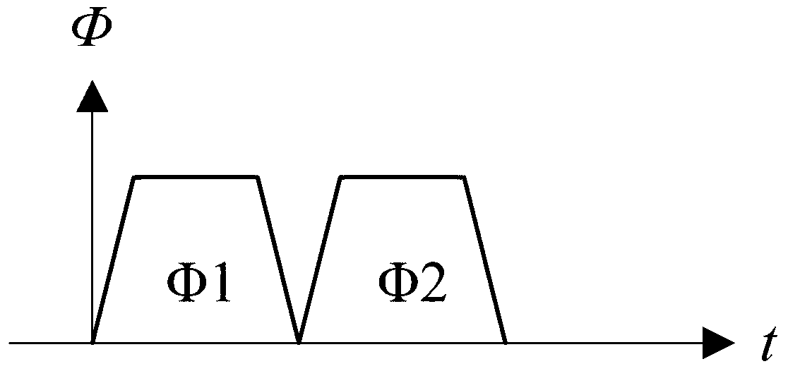
[0056] To sum up, the output voltage of the differential capacitance readout circuit in the prior art has a nonlinear relationship with the displacement of the mass block, and there is an electric spring effect

Method used


Image

  • Capacitance reading circuit of inertia detecting element
  • Capacitance reading circuit of inertia detecting element
  • Capacitance reading circuit of inertia detecting element

Examples


Embodiment Construction

[0090] In order to make the above objects, features and advantages of the present invention more comprehensible, specific implementations of the present invention will be described in detail below in conjunction with the accompanying drawings.

[0091] see Image 6 , which is a schematic diagram of Embodiment 1 of the capacitance readout circuit of the inertial detection element provided by the present invention.

[0092] The capacitance readout circuit of the inertial detection element provided in this embodiment includes: a preamplifier Ap1, a first sample holder 600, a second sample holder 700 and a differential amplifier Ap2;

[0093] G b is the gain of the preamplifier Ap1; G i is the gain of the differential amplifier Ap2.

[0094] The input end of the preamplifier Ap1 is connected to the signal output end of the inertial detection element, and the output end of the preamplifier Ap1 is connected to the first sample holder 600 and the second sample holder 700; the prea...


PUM


Abstract

The invention provides a capacitance reading circuit of an inertia detecting element. The capacitance reading circuit is characterized in that the input end of a pre-amplifier is connected with the signal output end of the inertia detecting element, and the output end of the pre-amplifier is connected with a first sampling holder and a second sampling holder. The pre-amplifier is used for pre-amplifying output signals of the inertia detecting element, and then outputs the signals to the first sampling holder and the second sampling holder. The output end of the first sampling holder is connected with the first input end of a differential amplifier, and the output end of the second sampling holder is connected with the second input end of the differential amplifier. The first sampling holder transmits the output signals of the inertia detecting element to the first input end of the differential amplifier, and the second sampling holder transmits the output signals of the inertia detecting element to the second input end of the differential amplifier. The output voltage of the differential amplifier is a voltage signal of the inertia detecting element. The output voltage of the capacitance reading circuit and displacement of a mass block are in linear relation, and an electrical spring effect does not exist.

Description

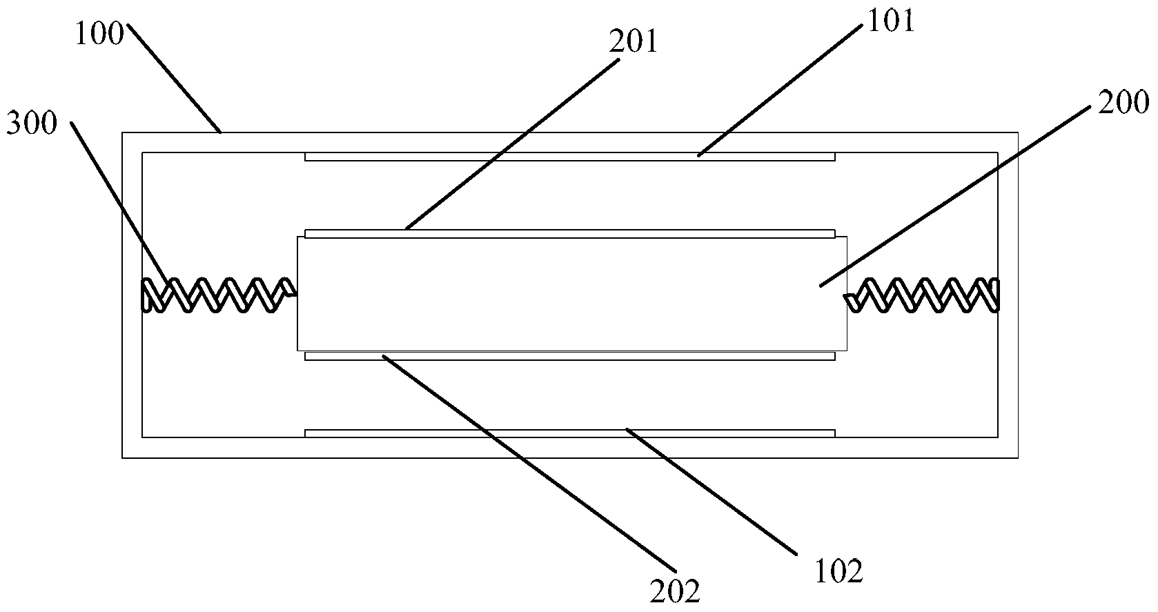
technical field [0001] The invention relates to the technical field of inertial detection, in particular to a capacitance readout circuit of an inertial detection element. Background technique [0002] Inertial detection components generally include inertial sensitive components such as acceleration sensors and gyroscopes. These inertial detection components measure the acceleration of the vehicle relative to the ground and other parameters in real time to determine the position of the vehicle and the parameters of the earth's gravity field. [0003] The MEMS (Micro Electro Mechanical System) acceleration sensor is taken as an example to introduce below. [0004] The MEMS acceleration sensor is an inertial detection element formed on a silicon wafer through a micromachining process. The mechanical structure of a typical MEMS acceleration sensor is a mass block-spring structure. Such as figure 1 As shown, the proof mass 200 is suspended in the frame 100 of the inertial det...

Claims


Application Information

Patent Timeline
Patent Type & Authority Applications(China)
IPC IPC(8): G01P15/125G01C19/5776
Inventor 韩可都冯方方董旸
Owner INST OF GEOLOGY & GEOPHYSICS CHINESE ACAD OF SCI
Learn More