
Combined support device of magnetic bearing rotor system

A magnetic levitation bearing and support device technology, applied to bearings, shafts and bearings, mechanical equipment, etc., to achieve the effect of suppressing vibration and good damping performance

Inactive Publication Date: 2013-09-18
NANJING UNIV OF AERONAUTICS & ASTRONAUTICS
View PDF6 Cites 14 Cited by
  • Summary
  • Abstract
  • Description
  • Claims
  • Application Information

AI Technical Summary

Problems solved by technology

This non-linear change of metal rubber stiffness makes it difficult to use metal rubber dampers alone to support the rotor system to control the critical speed of the system and meet the requirements of the design criteria for the critical speed of the rotor system.

Method used


Image

  • Combined support device of magnetic bearing rotor system
  • Combined support device of magnetic bearing rotor system
  • Combined support device of magnetic bearing rotor system

Examples


Embodiment 1

[0035] A combined support device for a magnetic suspension bearing rotor system, comprising a machine base, a rotor assembly and a magnetic suspension bearing assembly, the rotor assembly is supported by the magnetic suspension bearing assembly, the magnetic suspension bearing assembly is supported by a squirrel-cage elastic support device, and the squirrel-cage elastic support device is composed of a machine Seat support, a metal rubber ring is also arranged between the squirrel-cage elastic support device and the machine base.

Embodiment 2

[0037] On the basis of embodiment 1, the preferred technical scheme of the present invention is:

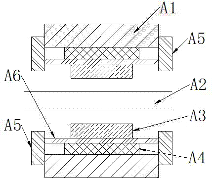
[0038] Such as figure 1 , a combined support device for a magnetic suspension bearing rotor system, comprising a machine base A1, a rotor assembly A2 and a magnetic suspension bearing assembly A3, the rotor assembly A2 is supported by the magnetic suspension bearing assembly A3, the magnetic suspension bearing assembly A3 is supported by a squirrel-cage elastic support device, and the squirrel cage The cage-type elastic support device is supported by the base A1, and a metal rubber ring A4 is also arranged between the squirrel-cage elastic support device and the base A1. The squirrel-cage elastic supporting device includes two end rings A5 and several cage bars A6, the two end rings A5 are respectively directly or indirectly fixed to the base A1, and each cage bar A6 is directly or indirectly fixed to the magnetic suspension bearing assembly A3.

Embodiment 3

[0040] On the basis of embodiment 1, the preferred technical scheme of the present invention is:

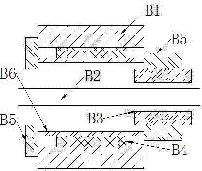
[0041] Such as figure 2 , a combined support device for a magnetic suspension bearing rotor system, comprising a base B1, a rotor assembly B2 and a magnetic suspension bearing assembly B3, the rotor assembly B2 is supported by a magnetic suspension bearing assembly B3, and the magnetic suspension bearing assembly B3 is supported by a squirrel-cage elastic support device, the squirrel cage The cage type elastic supporting device is supported by the machine base B1, and a metal rubber ring B4 is also arranged between the squirrel cage type elastic supporting device and the machine base B1. The squirrel-cage elastic support device includes two end rings B5 and several cage bars B6, one end ring B5 is directly or indirectly fixed to the base B1, and the other end ring B5 is directly or indirectly fixed to the magnetic suspension bearing assembly B3.


PUM


Abstract

The invention discloses a combined support device of a magnetic bearing rotor system. The combined support device comprises a base, a rotor assembly and a magnetic bearing assembly, wherein the rotor assembly is supported by the magnetic bearing assembly, the magnetic bearing assembly is supported by a squirrel-cage type elastic support device, the squirrel-cage type elastic support device is supported by the base, and a metal rubber ring is arranged between the squirrel-cage type elastic support device and the base. The combined support device of the magnetic bearing rotor system, provided by the invention, is capable of effectively inhibiting the vibration of a high-speed magnetic bearing rotor system. According to the combined support device, good damping property of a metal rubber material can be effectively utilized, the rotating speed of the rotor system can be controlled so as to meet the requirement of a design criteria of critical speed of rotation of the rotor system, and a magnetic bearing is favorably popularized and applied.

Description

technical field [0001] The invention relates to a combined support device for a magnetic suspension bearing rotor system. Background technique [0002] Compared with the rotor system supported by traditional bearings, the magnetic suspension bearing rotor system has many incomparable advantages because of the non-contact between the magnetic suspension bearing and the rotor it supports. [0003] The magnetic suspension bearing suspends the rotor by generating electromagnetic force, which can be controlled by adjusting the coil current or voltage, that is, the stiffness and damping of the magnetic suspension bearing are controllable, so the vibration of the rotor can be suppressed within a certain range. [0004] However, the magnetic suspension bearing rotor system has a narrow adjustment range for its own stiffness and damping, and its damping is relatively low, which makes its ability to suppress rotor vibration weak, especially when the rotor crosses the critical speed an...

Claims


Application Information

Patent Timeline
Patent Type & Authority Applications(China)
IPC IPC(8): F16C32/04
Inventor 张发品周瑾徐龙祥金超武吉敏来
Owner NANJING UNIV OF AERONAUTICS & ASTRONAUTICS
Learn More