
Adjustable locking mechanism

A locking mechanism and locking block technology are applied in the direction of friction-clamped detachable fasteners, connecting components, mechanical equipment, etc., and can solve the problems of adjusting the locking force, the thickness of the inclined surface is not adjustable, and the use is inconvenient. To achieve the effect of locking force

Active Publication Date: 2015-07-15
JIANGXI HONGDU AVIATION IND GRP
View PDF7 Cites 0 Cited by
  • Summary
  • Abstract
  • Description
  • Claims
  • Application Information

AI Technical Summary

Problems solved by technology

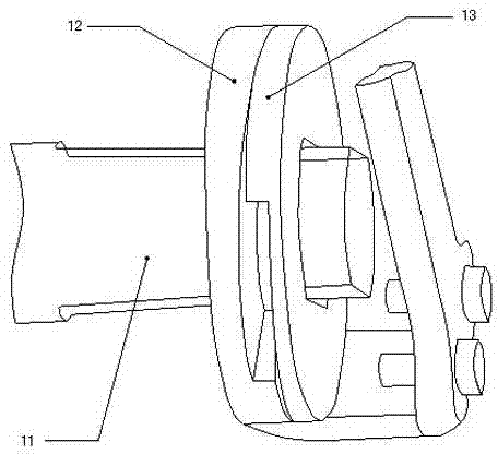
[0004] During use, the user found that the existing locking mechanism has at least the following problems: the locking effect on the throttle lever mainly comes from the extrusion effect caused by the axial displacement of the movable locking block, the greater the axial displacement , the stronger the locking effect, and the size of the axial displacement is related to the slope thickness of the movable locking block and the fixed locking block, and the thickness of the slope cannot be adjusted. In this way, the user cannot adjust accordingly according to the actual situation. The size of the locking force, the scope of use is limited, and it is not convenient to use

Method used


Image

  • Adjustable locking mechanism
  • Adjustable locking mechanism
  • Adjustable locking mechanism

Examples


Embodiment Construction

[0019] The specific implementation manners of the present invention will be further described in detail below in conjunction with the accompanying drawings and embodiments. The following examples are used to illustrate the present invention, but are not intended to limit the scope of the present invention.

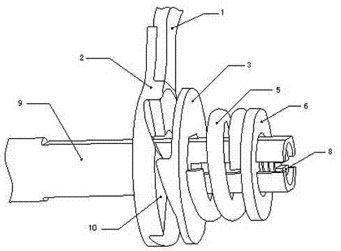
[0020] like figure 2 and image 3 As shown, the adjustable locking mechanism of the present invention includes a connecting shaft 9, a movable locking block 2 and a fixed locking block 3, and the movable locking block 2 is in contact with the fixed locking block 3 and can rotate relatively. The contact surface of the tight block 2 matches the contact surface of the fixed locking block 3, and also includes a locking screw 8, a spring 5 and a retaining ring 6, and the movable locking block 2, the fixed locking block 3, the spring 5 and the retaining ring 6 are sequentially Set on the connecting shaft 9, one end of the spring 5 is in contact with the fixed locking block 3,...


PUM


Abstract

The invention relates to the technical field of locking mechanisms, in particular to an adjustable locking mechanism. The adjustable locking mechanism is adjustable in locking force and further comprises a locking screw, a spring and a check ring; a movable locking block, a fixed locking block, the spring and the check ring are embedded on a connecting shaft in sequence; one end of the spring is connected with the fixed locking block, and the other end of the spring is connected with the check ring; the locking screw is installed on the connecting shaft and connected with the check ring. The adjustable locking mechanism can be widely used for fastening or fixing elements.

Description

technical field [0001] The invention relates to the technical field of locking mechanisms, in particular to an adjustable locking mechanism. Background technique [0002] As we all know, the locking mechanism is a fastening or fixing element, a device that makes the element static at a predetermined position, and is widely used in mechanical control; the locking mechanism of the prior art will be used as a lock for the engine throttle lever in the following documents Take tight action as an example. [0003] see figure 1 , the locking mechanism of the prior art generally includes a connecting shaft 11, a movable locking block 12 and a fixed locking block 13, the movable locking block is sleeved on the connecting shaft, and the fixed locking block is fixed on the connecting shaft, and the movable locking block The tight block is in contact with the fixed locking block and rotates relatively. The contact surface of the movable locking block matches the contact surface of the...

Claims


Application Information

Patent Timeline
Patent Type & Authority Patents(China)
IPC IPC(8): F16B2/00
Inventor 范昱杨建勇晏莹古远康邓新华李子昂冯彬刘宁泉刘龙园毛哲苏育峰雷波
Owner JIANGXI HONGDU AVIATION IND GRP
Learn More