
An underground hydraulic oil pumping system

A power system and hydraulic power technology, which is applied in the field of downhole rodless hydraulic power pumping system to achieve the effects of improving system efficiency, overcoming friction and energy loss, and reducing energy loss

Inactive Publication Date: 2016-04-27
申素芝
View PDF1 Cites 0 Cited by
  • Summary
  • Abstract
  • Description
  • Claims
  • Application Information

AI Technical Summary

Problems solved by technology

[0003] The purpose of the present invention is to overcome the problems existing in the complex mechanical reversing system in the existing rodless hydraulic oil pumping system, and provide a device that relies on instructions, can achieve more precise control, has small energy loss, enhanced power, and at the same time has a simple structure and is easy to maintain. The downhole hydraulic power pumping system introduced the idea of ​​command and steering for the first time in this field

Method used


Image

  • An underground hydraulic oil pumping system
  • An underground hydraulic oil pumping system
  • An underground hydraulic oil pumping system

Examples


Embodiment 1

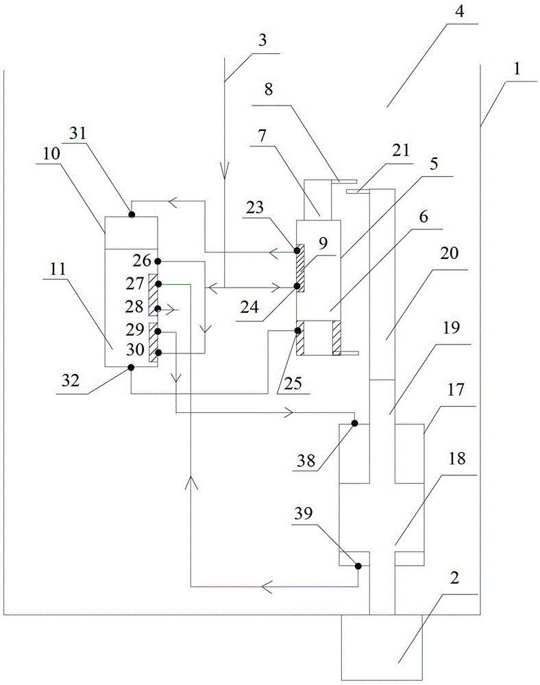
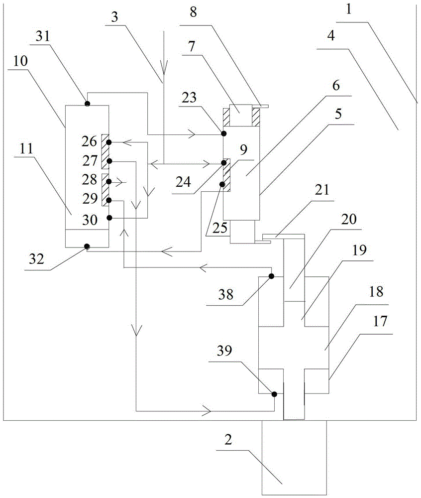
[0042]A downhole hydraulic power pumping system, including a power system, a command system and a steering system arranged in a tubing 1, the power system is connected to an oil well pump 2, and the tubing 1 has a power fluid channel 3 and a channel 4 for mixing the idle power fluid and the well fluid , the power system, command system and steering system are all structures with pistons in the cylinder;

[0043] The command system is a cylindrical cylinder, which is called the command cylinder 5, and the inside is provided with a piston that can slide up and down, called the command piston 6. The length of the command piston 6 is less than the length of the command cylinder 5, and the two ends of the command cylinder 5 Open, the two ends of the command piston 6 are respectively provided with a bump 7 with a cross-sectional area smaller than the cross-sectional area of ​​the command cylinder 5, and a hanging block 8 is respectively arranged on the bump 7, and a concave block 9 i...

Embodiment 2

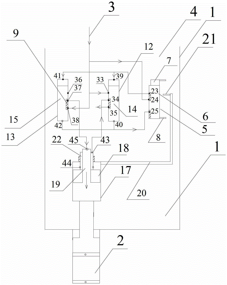
[0052] The difference from Embodiment 1 lies in the changes of the steering system and the power system, specifically:

[0053] The steering structure is two cylindrical cylinders, which are denoted as the first steering cylinder 12 and the second steering cylinder 13. The two steering cylinders are provided with pistons that can slide up and down, which are correspondingly denoted as the first steering cylinder. Steering piston 14 and the second steering piston 15, the length of the first steering piston 14 is 5 / 6 of the first steering cylinder 12, a concave block 9 is arranged in the middle of the first steering piston 14, and the On the cylinder block 12, from top to bottom, 1 / 3, 1 / 2, and 2 / 3 are provided with holes, which are denoted as the eleventh hole 33, the twelfth hole 34, and the thirteenth hole 35; Two steering cylinders 13 and the second steering piston 15 are identically arranged, and the holes on it are marked as the fourteenth hole 36, the fifteenth hole 37, an...


PUM


Abstract

The invention provides an underground hydrodynamic oil pumping system. The underground hydrodynamic oil pumping system comprises a power system, an instruction system and a steering system which are arranged inside an oil pipe, wherein the power system is connected with an oil-well pump, a power liquid channel and a power-lacking liquid and well fluid mixing channel are arranged inside the oil pipe, the power system, the instruction system and the steering system are in such structures that pistons are arranged inside cylinders, a plurality of holes are formed in the cylinders of the instruction system and the steering system, concave blocks are arranged on the pistons correspondingly, and the direction of a power liquid is changed by the aid of corresponding position relations of the holes and the pistons. The underground hydrodynamic oil pumping system has the advantages that the whole system is achieved by the aid of the power liquid completely, and the soft steering is achieved, so that friction and energy losses caused by mechanical steering are eliminated, and the service life is long; all pipelines in the steering system are located inside the liquid, and pressures inside and outside the pipelines are balanced, so that deformations caused by changing of inside and outside pressure differences are avoided, and energy losses are reduced; thus, according to the technical scheme, the energy can be used for lifting to the maximum extent, and the system efficiency can be improved to over 50%.

Description

technical field [0001] The invention relates to a petroleum mining machine, in particular to a downhole rodless hydraulic power pumping system. Background technique [0002] There are two types of oil pumping in oil fields: rod extraction and rodless extraction. The most common type of extraction with rods is the pumping unit, which is the most common and the most efficient pumping method at present, but the energy utilization rate of existing equipment is only about 35%. ; In the case that some ground conditions are not available, the rodless oil production method will be selected, but there are also situations where the energy utilization rate is not high. The present invention mainly relates to the field of rodless oil recovery. In this technical field, how to improve the utilization rate of energy is the key point. The reversing system is the key point of the technology. The use of spacers has complex mechanical mechanisms, inconvenient maintenance, and most of them are...

Claims


Application Information

Patent Timeline
Patent Type & Authority Patents(China)
IPC IPC(8): F04B47/04E21B43/00
Inventor 孙家谦孙宇
Owner 申素芝
Learn More