
Optical communication-based toy remote control system

A remote control system and optical communication technology, applied in the field of toy remote control systems, can solve the problems of other people's property or personal safety hazards, wireless electromagnetic wave remote control transmission distance, inconvenient integration of antenna devices, etc., to achieve improved use efficiency and rich spectrum resources Effect

Inactive Publication Date: 2013-09-11
KUANG CHI INTELLIGENT PHOTONIC TECH
View PDF6 Cites 1 Cited by
  • Summary
  • Abstract
  • Description
  • Claims
  • Application Information

AI Technical Summary

Problems solved by technology

On the one hand, the use of electromagnetic wave wireless remote control requires a relatively long antenna device on the remote control. The antenna device is not convenient to integrate into other toys, such as toy mobile phones; on the other hand, the transmission distance of wireless electromagnetic wave remote control is relatively long. When playing with cars or toy airplanes, due to the long electromagnetic wave transmission distance, children will inadvertently take the toy airplane or toy car out of sight, which will easily cause the loss of the toy airplane or toy car, and also easily make the toy airplane or toy car out of sight cause property or personal safety hazards to others

Method used


Image

  • Optical communication-based toy remote control system
  • Optical communication-based toy remote control system
  • Optical communication-based toy remote control system

Examples


Embodiment Construction

[0020] The following will clearly and completely describe the technical solutions in the embodiments of the present invention with reference to the accompanying drawings in the embodiments of the present invention. Obviously, the described embodiments are only some, not all, embodiments of the present invention. Based on the embodiments of the present invention, all other embodiments obtained by persons of ordinary skill in the art without creative efforts fall within the protection scope of the present invention.

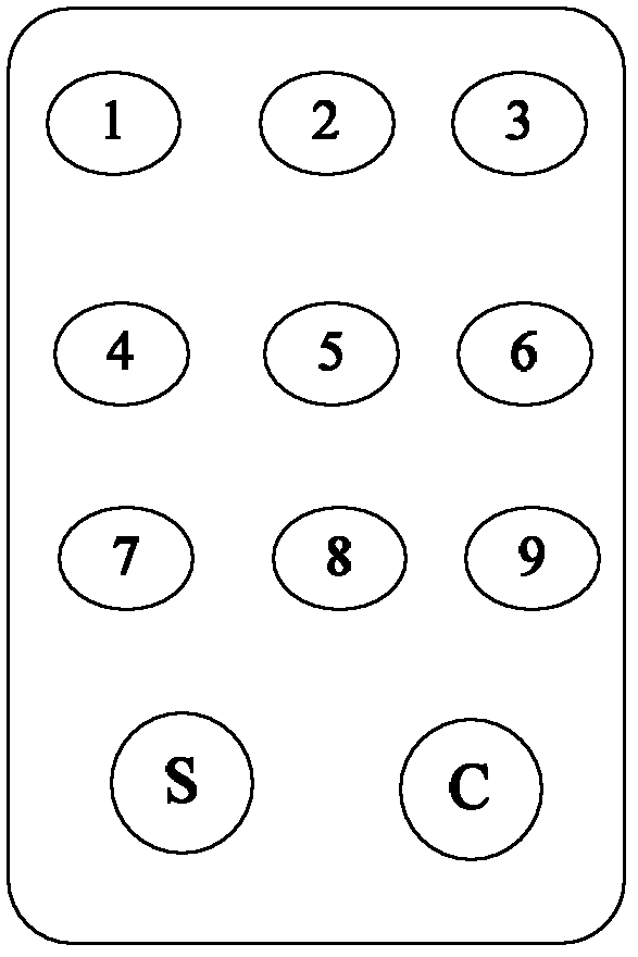
[0021] Please refer to figure 1 , figure 1 It is a schematic structural diagram of the toy remote control system based on optical communication of the present invention. figure 1 In this system, the system includes an optical signal transmitting system 1 and an optical signal receiving and processing system 2. The optical signal transmitting system 1 transmits the user's operation instructions in the form of visible light, which can be LED light; multiple optical...


PUM


Abstract

The invention discloses an optical communication-based toy remote control system which comprises an optical signal emitting system used for emitting an optical signal according to a user command, and an optical signal receiving and processing system arranged on a remote control toy, wherein the optical signal receiving and processing system comprises an optical signal detection module used for detecting the optical signal and converting the optical signal into a current signal, a voltage signal conversion module used for converting the current signal into a voltage signal, a digital signal obtaining module used for converting the voltage signal into a digital signal, a decoding module used for decoding the digital signal into a user command, and a signal judging module used for controlling the action of the remote control toy according to the user command. The optical communication-based toy remote control system realizes a remote control function of a toy car or a toy plane by adopting a visible light communication mode; compared with an electromagnetic wireless remote control mode, the optical communication-based toy remote control system has the advantage that the remote control module, namely the optical signal emitting system, can be integrated in various common toys for children without additionally setting an antenna.

Description

technical field [0001] The invention relates to the technical field of optical communication, in particular to a toy remote control system based on optical communication. Background technique [0002] With the development of the economy, children in the family have more and more toys, such as toy mobile phones, remote control toy cars, and remote control toy airplanes. [0003] Existing remote control toys all need their own remote control, and usually adopt the mode of electromagnetic wave wireless remote control. On the one hand, the use of electromagnetic wave wireless remote control requires a relatively long antenna device on the remote control. The antenna device is not convenient to integrate into other toys, such as toy mobile phones; on the other hand, the transmission distance of wireless electromagnetic wave remote control is relatively long. When playing with cars or toy airplanes, due to the long electromagnetic wave transmission distance, children will inadver...

Claims


Application Information

Patent Timeline
Patent Type & Authority Applications(China)
IPC IPC(8): G08C23/04A63H30/04
Inventor 刘若鹏栾琳刘敏周梦娜张剑
Owner KUANG CHI INTELLIGENT PHOTONIC TECH
Learn More