
Elevator system

An elevator system and elevator car technology, applied in elevators, transportation and packaging, etc., can solve the problems of insufficient wiring reduction, inability to carry out all communications, inability to ensure elevator functions, etc., and achieve the effect of reducing the number of cables and suppressing the loss of functions.

Active Publication Date: 2013-09-11
MITSUBISHI ELECTRIC CORP
View PDF10 Cites 12 Cited by
  • Summary
  • Abstract
  • Description
  • Claims
  • Application Information

AI Technical Summary

Problems solved by technology

[0007] However, in the elevator system described in Patent Document 1, only signals related to safety control are bused (serialized), so there is a problem of insufficient wiring reduction.
In addition, even if other signals are bused in the same way, there is a problem that the function of the elevator cannot be ensured when a communication error occurs
[0008] Moreover, in the elevator system described in Patent Document 2, when a communication error occurs or wireless communication cannot be performed due to a power outage, etc., all communication cannot be performed, so there is a problem that the elevator function cannot be ensured.

Method used


Image

  • Elevator system
  • Elevator system
  • Elevator system

Examples


Embodiment approach 1

[0022]

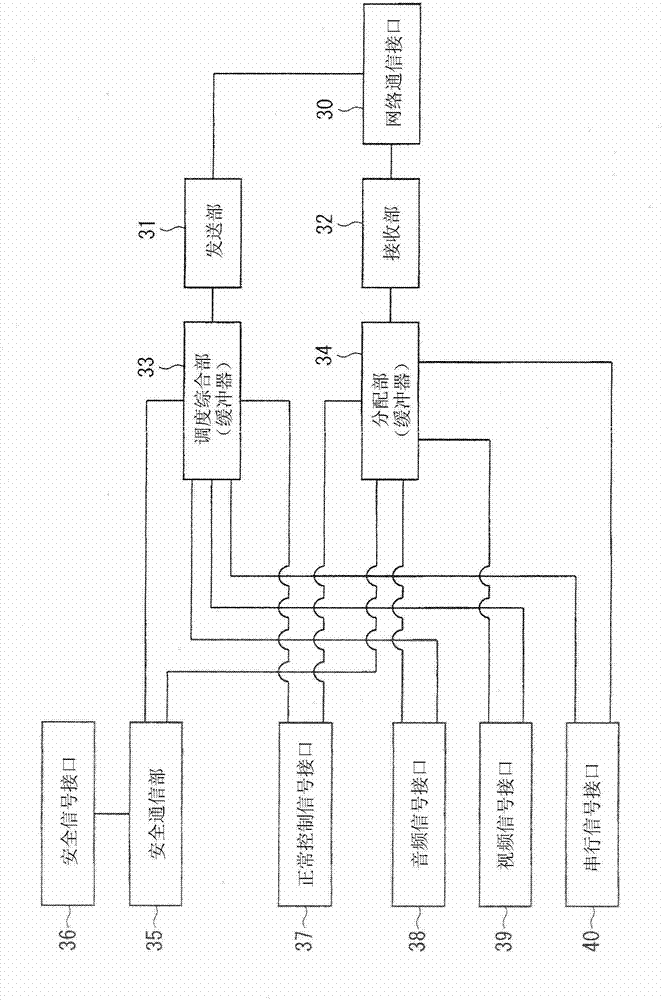
[0023] figure 1 It is a figure which shows the structure of the elevator system in Embodiment 1 of this invention. The elevator system has a car 5 and a control panel 4 that controls the operation of the car 5 . The control panel 4 has a communication controller 1a, and the car 5 is provided with a communication controller 1b connected to the communication controller 1a via a network 2 for parallel communication and a communication line 3 for serial communication. In addition, here, an embodiment of two communication controllers is shown, but the number of communication controllers is not limited to this, and may be three or more.

[0024] The car 5 is provided with an intercom 13b for audio input and output, a safety switch sensor 15, a normal control switch sensor 16, a monitoring camera 17, a monitor 18, a card reader 19 for a serial communication device providing a security function, and a door control system. Various elevator equipment such as device 20, door...

Embodiment approach 2

[0071] Figure 7 It is a block diagram showing the structure of the elevator system of Embodiment 2. The elevator system according to Embodiment 2 includes, in addition to the configuration of the elevator system according to Embodiment 1, a communication controller 1c provided in a hoistway 23, a hoistway switch 25, a door switch 24 at a hall, and a safety control device 6c.

[0072] In the elevator system of the present embodiment, each of the control panel 4, the car 5, and the hoistway 23 is equipped with a communication controller and a safety control device, and these safety control devices implement respective safety controls. At this time, the communication controllers 1a, 1b, and 1c communicate with each other about the information of the elevator equipment connected to each other, so that the safety control devices 6a, 6b, and 6c connected to the communication controllers 1a, 1b, and 1c can share the information of the elevator equipment. information while implement...


PUM


Abstract

The object of the present invention is to provide an elevator system that reduces wires and suppresses a loss of functions even in an abnormal state. The elevator system of the present invention includes: a communication controller (1b) that is installed in a cage (5), an elevating path, or a platform, and connected to an elevator equipment inside the cage (5), an elevator equipment inside the elevating path or an elevator equipment of the platform; a communication controller (1a) that is connected to the communication controller (1b) through a serial communication network (2) and an individual communication line (3) so as to perform communication; and control means that is connected to the communication controller la so as to control operations of the cage (5), in which the individual communication line communicates a signal individually in a manner separated from a signal communicated through the network (2).

Description

technical field [0001] The present invention relates to the communication technology of the elevator system. Background technique [0002] In the conventional elevator system, since various elevator devices such as switches and sensors are connected to the control board separately, the amount of wiring is enormous. [0003] Therefore, Patent Document 1 discloses a technique for reducing wiring by connecting devices related to safety control to bus nodes in various elevator installations, and connecting the bus nodes and safety controllers via a safety bus. [0004] Furthermore, Patent Document 2 discloses a technique for reducing wiring by making various signals of elevator equipment wireless. [0005] [Patent Document 1] Japanese National Publication No. 2002-538061 [0006] [Patent Document 2] Japanese Patent Laid-Open No. 2004-48474 [0007] However, in the elevator system described in Patent Document 1, only signals related to safety control are bused (serialized), an...

Claims


Application Information

Patent Timeline
IPC IPC(8): B66B1/06B66B5/00
CPCB66B1/3423B66B5/0031B66B1/06B66B3/00
Inventor 鹫尾和则高桥理北山健志滨田和树
Owner MITSUBISHI ELECTRIC CORP
Learn More