
Winding device and printing device

A technology of winding shafts and planetary gears, applied in printing and inking devices, etc., can solve the problems of complex structure of tape winding mechanism and increase of manufacturing cost, and achieve the effect of reducing quantity and reducing manufacturing cost

Inactive Publication Date: 2013-09-11
OKI ELECTRIC IND CO LTD
View PDF9 Cites 0 Cited by
  • Summary
  • Abstract
  • Description
  • Claims
  • Application Information

AI Technical Summary

Problems solved by technology

However, if the number of gears constituting the tape winding mechanism increases, not only the structure of the tape winding mechanism becomes complicated, but also there are problems in ensuring the installation space of the tape winding mechanism in the device and increasing the manufacturing cost.

Method used

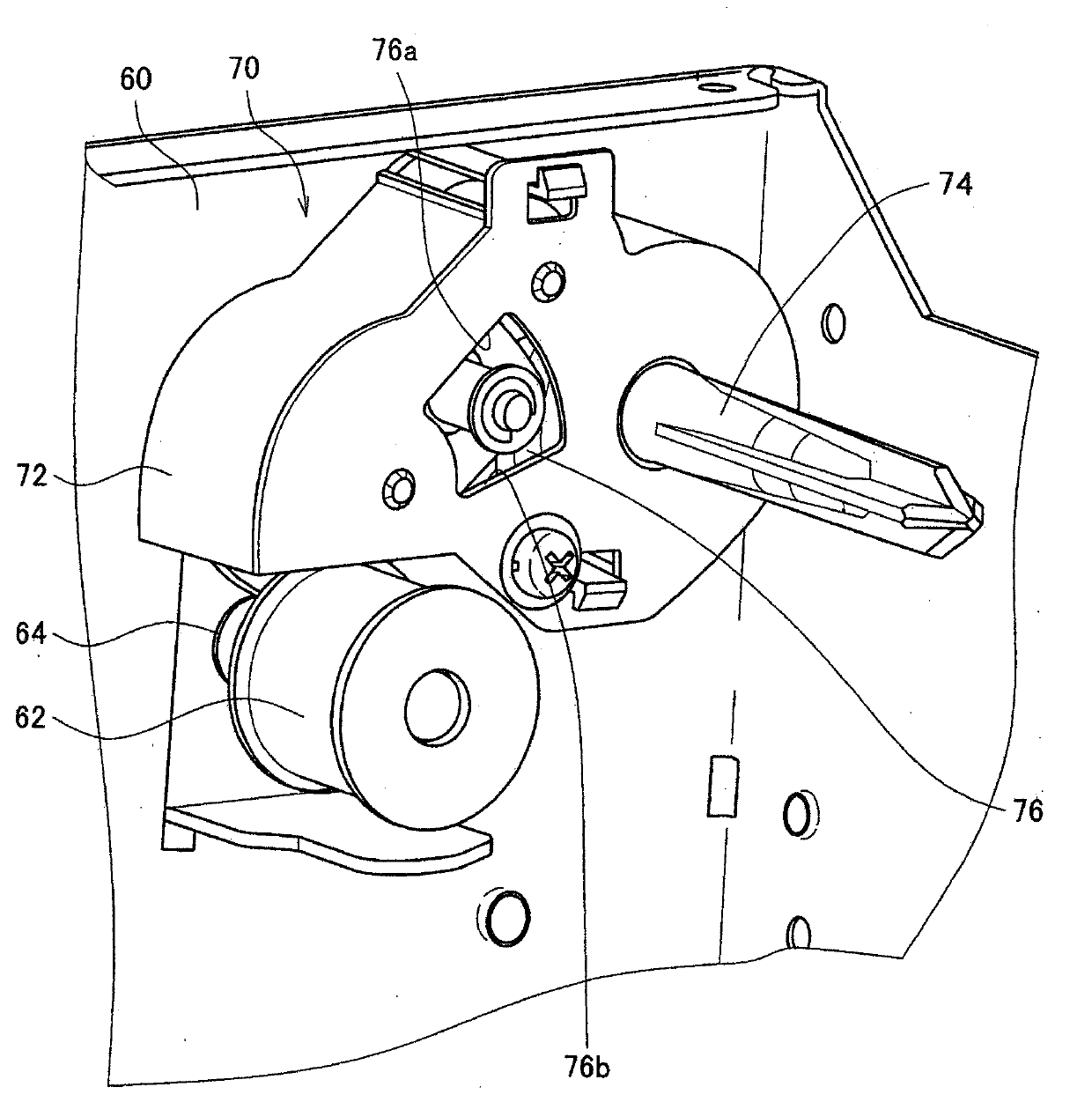

Image

  • Winding device and printing device
  • Winding device and printing device
  • Winding device and printing device

Examples


Embodiment Construction

[0027] Embodiments of the present invention will be described in detail below with reference to the drawings. However, in this specification and the drawings, components having substantially the same functional configuration are denoted by the same reference numerals, and repeated descriptions are omitted.

[0028] In addition, in this specification and the drawings, a plurality of constituent elements that actually have the same functional configuration may be distinguished by attaching different letters to the same reference numerals. However, when there is no particular need to distinguish a plurality of constituent elements that actually have the same functional configuration, only the same reference numerals are attached.

[0029]

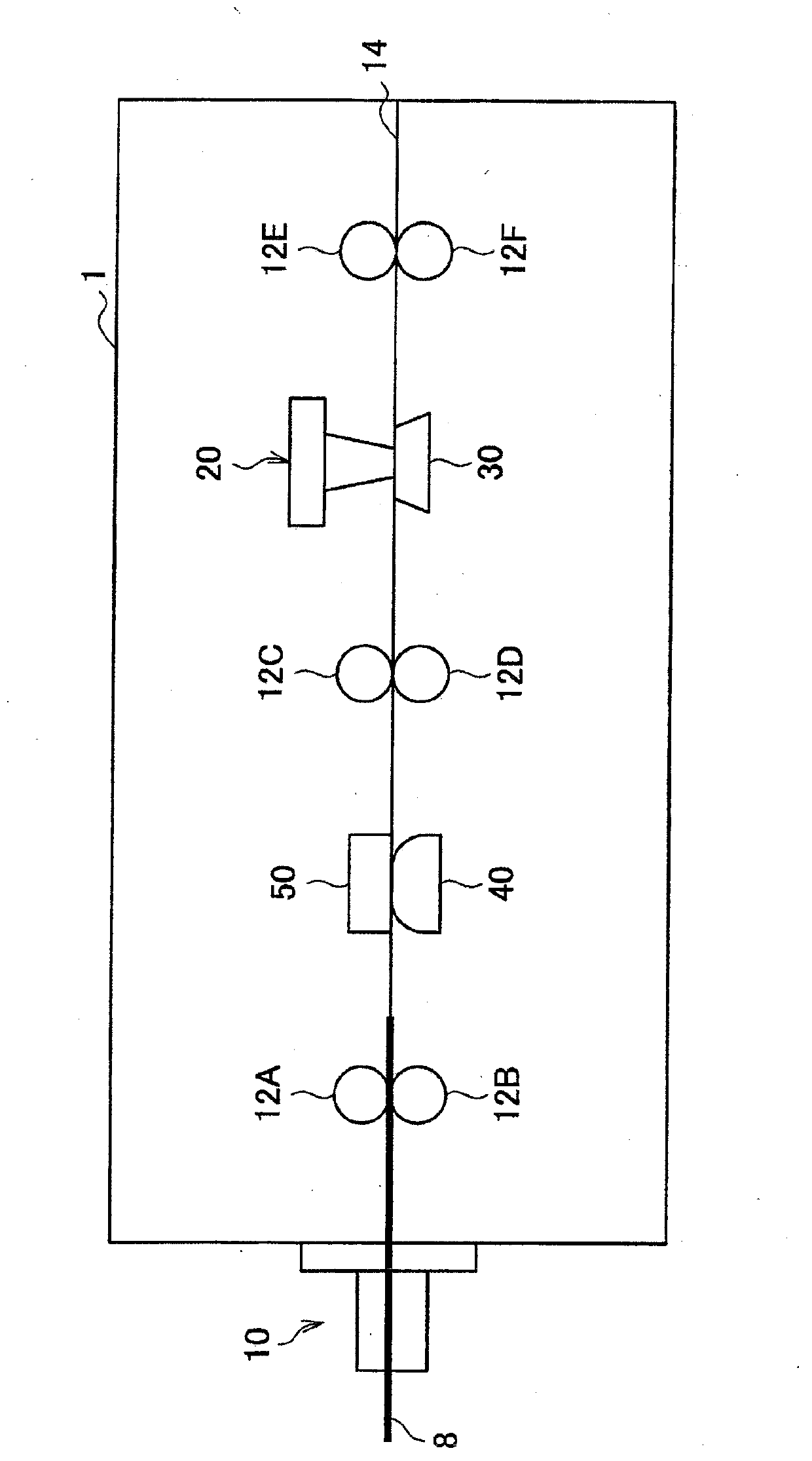
[0030] The present invention can be implemented in various forms as explained in detail below as an example. In addition, in the printing device 1 according to the embodiment of the present invention,

[0031] A. A printing unit ( 20 ) is ...


PUM


Abstract

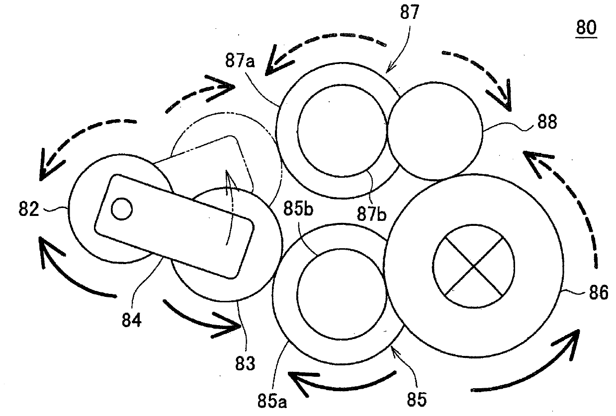
The present invention provides a winding device and a printing device. The winding device can reduce the number of gears for winding tapes. The winding device includes: a sun gear, which is engaged with a drive gear; a planetary gear which is engaged with the sun gear and moves around a rotational axis of the sun gear; and a winding gear, which includes a winding shaft for printing tapes in a central axis, is engaged with the planetary gear through the movement of the planetary gear to a first position, and thus is interlinked with the planetary gear and rotated.

Description

technical field [0001] The present invention relates to a tape winding device and a printing device. Background technique [0002] Recently, various printing devices for printing or printing characters, images, and the like on paper media are widespread. This printing device has, for example: a platen supporting a paper medium, and a printing head reciprocating along a predetermined moving direction. to print on. [0003] In addition, the printing device includes a tape winding mechanism for winding the ink ribbon. The tape take-up mechanism rotates a take-up shaft of the ink ribbon based on a rotational drive force transmitted from a drive gear fixed to a drive motor that drives the print head. Here, the drive motor rotates in the first direction and the second direction opposite to the first direction to reciprocate the print head. Therefore, the tape winding mechanism, as described in Patent Document 1 and Patent Document 2, is responsible for winding the ink ribbon e...

Claims


Application Information

Patent Timeline
Patent Type & Authority Applications(China)
IPC IPC(8): B41J33/22
Inventor 中岛智纪
Owner OKI ELECTRIC IND CO LTD
Learn More